1 Introduction
In the presented thesis, we perform research
in the areas of resource access management in the Internet, distributed
architectures for laboratory-based e learning and didactics for e-learning
laboratories. We propose a novel architecture for resource access management;
two novel distributed e-learning architectures and a didactical framework.
The Internet has opened new possibilities in
many areas of our daily life. Among others, educational institutions are
involved in these changes. Educational institutions own learning resources,
which they have made available in a traditional way but now, also have to be
made available on the Internet. When we use the term traditional learning
throughout this document, we refer to course resources as for example lectures
or hands-on trainings held in universities. Hence, the Internet has opened new
ways for providing these resources to the student community. The word resource
in this context is a generic term, which stands for any kind of courses,
lectures, seminars, or trainings.
During this process, a new term has been
established: electronic-learning or in brief, e-learning. E-learning is the
generic term for imparting any kind of learning resources by the Internet and a
new form of distance learning. We use the term e-learning resources throughout
this document for all resources users can access with web browsers.
There are two entities interacting in
e-learning scenarios: The first entity consists of resource providers and
tutors in elementary, secondary and high schools, colleges, and universities as
well as in commercial educational institutes. The second entity consists of the
students, which belong to the mentioned educational institutes. Some students
use the resources as a part of their compulsory curriculum; others desire
further education in the process of life long learning, some to achieve a
higher grade or to improve their knowledge. Other students are handicapped
persons who cannot easily travel around and persons from developing countries
with a poor educational infrastructure.
For e-learning users the underlying infrastructure,
such as course platforms, reservation systems, authentication systems,
databases and more, grouped together in e-learning architectures, should remain
almost invisible. Users only get into contact with web interfaces for using
these systems. Well-designed e-learning resources offer user-friendly access
management to all elements of the architecture. These e-learning resources
should provide the necessary access credentials in a user-friendly way. For resource
operators, well working interactions between the elements of an e-learning
architecture are of fundamental nature. The diversity of the theoretically
available protocols and applications in the Internet, usable for an e-learning
architecture, raises questions related to the desired interoperability and
user-friendliness, which scientists must further investigate.
The production and maintenance of e-learning
resources is expensive and it is thus necessary to restrict access to a limited
set of subscribed students. In addition to restricting access to the resources,
there is also a demand for adding supplementary features. Many traditional
resource providers who start activities in e-learning first try to make their existing
study materials available on the Internet in a one to one transformation
process, instead of applying a didactical framework designed for e-learning
resources. They put the content of existing books or scripts on web pages without
minimal enhancements or adaptations. This procedure does not use the didactical
possibilities of e-learning and the potential for improving the teaching
quality. However, it is possible to achieve good results with the application
of a didactical framework, which specifies the course structure and the
didactical methods.
Chapter 1.2 introduces into the basics of e-learning architectures
and resource access management, necessary for the understanding of the
investigated problems and approaches. Chapter 1.3 introduces into the basics of didactics in e-learning
courses, considered necessary for the later discussion and understanding of the
investigated problems and approaches. Chapter 1.4 presents the encountered problems together with our
contributions performed in this thesis. Chapter 1.5 gives a brief outline of the thesis.
When considering a traditional learning resource, for example a
textbook, we discover that there are many elements necessary before a student
starts learning with the book. An author has to write the text, a printer to
make the book, a bookshop to sell the book and a tutor to recommend the book
for a lecture. Similar actors, such as the author and an illustrator but also
much more technical elements are necessary for the production of an e-learning
resource, which consists of a minimal technical infrastructure. We can split up
this infrastructure into three parts:
Systems for resource
providing
Resource providers host their resources on web servers,
connected to the Internet. Depending on the resource, the web servers feature different
types of services, such as for providing dynamic Hypertext Markup Language
(HTML) pages [Bv45 and BC95]. The World Wide Web Consortium (W3C) HTML specification
defines the representation format for pages with textual information and
Systems for data transport
In e-learning, the Internet is typically the part of the
infrastructure, which transports the resource data between resources and
students and between the elements of a resource. In the strict sense, each
computer or device connected to the Internet makes part of it, also the
equipment for resource providing and studying. In this context, we refer to the
wires, routers [Pr00] and devices between the resource servers and the students,
which transport the data. Routers are devices in packet switched networks [Gp80]
such as the Internet, which forward data packets to the next hop towards its
destination. Internet Service Providers (ISP) supply this part of the
infrastructure. Internet service providers are organizations, which sell data
transport capacity and Internet services to their customers.
Systems for students and
tutors
Students and tutors who use e-learning resources for their
study purposes and teaching must have access to a computer with Internet
connectivity. Depending on the services offered by the resource provider, the
computer must be equipped with applications that allow benefiting from these
services. Students have to make sure that their Internet access has enough data
transport capacity to be able to use the offered services.
Architectures for Internet-based resources describe the design
and the functionalities of the future implementations. Consequently, an
e-learning architecture is an architecture, which describes the design and the
functionalities of all the necessary elements for the operation of an e-learning
resource. In other words, e-learning architectures define the data exchange
between users, comprising students, tutors and administrators and the elements
responsible for the operation of the course system, comprising content servers
and course management system.
Figure
1‑1 shows frequently used elements of e-learning
architectures whereas Table
1‑1 discusses them. Required elements are clients, which
connect via the Internet to the resource elements. Clients contact servers in
the technical meaning and utilize services in the technical and commercial
meaning. Such clients can be users such as students, tutors, and
administrators. The resource management system is another required element in
the case of resources with controlled user access. It manages the user accounts
for students, tutors and the resource access issues as well as the resource
content servers, which provide web pages, audio streams, video streams, and
communication services to the students.
One resource content server is at least required in any
e-learning architecture and further resource content servers are optional. More
than one resource content server is useful for load balancing, for example by
geographically distributing the servers around the globe or for forming an
e-learning grid, enabling a variety of resource providers to operate their
respective servers at their home locations. A single resource provider, which
joins such an e-learning grid contributes the own learning content to the
community and gets access to the content of the grid partners. This restricts the
maintenance and update processes to the own resources. An optional element in
an e-learning architecture is a resource reservation system. A resource
reservation system is only necessary if certain resources do not exist in
sufficient quantities for all the resource students who would like to access
the respective resource at the same time.
|
Element |
Function |
Presence |
|
Resource |
User accounts are stored on resource management systems.
Resource management systems control user access to connected content servers
and reservation systems. The resource management system performs accounting
for the user interactions with the single elements of the architecture. Some resources use applications with a limited user access
capacity. In such cases, the resource management system must contain a
reservation system. Students have to pre-register (book) their sessions with
the reservation system. |
Required, |
|
Students, tutors, administrators |
Tutors and students access the resource management system and
other elements that make part of the resource. |
Required |
|
Resource |
Learning content is stored on resource content servers. At
least one resource content server is required in an e-learning architecture.
The server can be a part of the resource management system, and then it is a
course platform. Distributed resource content servers can provide their
content via a resource management system and form one distributed resource. |
One |
Table 1‑1: E-learning architecture elements.
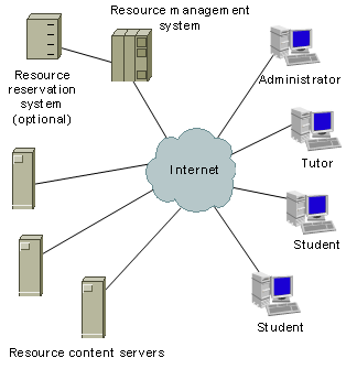
Figure 1‑1: E-learning architecture elements.
An administrator or tutor
registers the students with the resource management system. The resource
management system registers those students automatically with the optional
resource reservation system and with the resource content servers. Each element
of the architecture interacts with the other corresponding elements. Clients,
in the meaning of the client/server principle [Cb96 and SRC84] connect to the
resource management system, to the resource content servers and to the
reservation system. The resource management system interacts with the resource
content servers and with the reservation system. Resource content servers, which
provide limited software or hardware resources, interact with the reservation system.
Students can access resources, which provide limited hardware and software
resources only upon anterior reservation.
After the introduction of
the general aspects of e-learning architectures, we introduce centralized and
distributed content providing architectures, respectively. Many Internet services,
used to provide information to users, are physically located on servers in one
central location. This is a historical consequence: at the beginning of the computer
era, there was one server room per organization and it was not possible to
operate servers at other locations. These are centralized architectures. Architectures,
integrating servers distributed over multiple locations are distributed
architectures. Such distributed architectures, for example in the case of an
e-learning architecture, make use of distributed content providing servers, of
the resource management system to integrate resource content from the different
servers and provide it under one identity to the students. However, the resource
management system has to manage the student access for all resource content
partners. The resource management system can integrate distributed student registration
and access procedures for the connected resource partners, for example performed
with their respective administrations. In the distributed architecture, the
resource management system and one resource content server are in location X
with a second content server in place Y, a third in place Z, whereas in the
centralized architecture all servers are in place X. The students, tutors, and
administrators can be everywhere where they have Internet connectivity.
Didactics is the science of guided education comprising several areas, ranging from general principles and frameworks of educating to special methods for different learning tasks [Gh96]. The didactical framework decides on how successful students finish the course. Most tutors are well educated for teaching in traditional classrooms but not for teaching with e-learning resources. The new teaching environment internationalizes the audience, which bears reasons for conflicts in cultural and social belongings.
There are many details in the design of a resource that can lead to a complete misunderstanding by the students [Ss99], for example, colors can have differing meanings from culture to culture. The design of a resource must also respect the fact that different individuals use different ways for studying [PKR00 and PKRO98]. Additionally, one should consider learning differences caused by religious, ethnic, cultural and gender diversity of students, which influence the process of collaborative activity within groups [CGLO02]. Thus, authors have to design their resources for their future audience.
An advantage in e-learning is the possibility to include instantly available optional and supplementary study material or to add pointers to such material. By these means, students who do not fit the minimal knowledge requirements for the respective resource can work through the resource all the same.
Learning without face-to-face contact is not new to humanity.
Only the trend has changed towards non-face-to-face learning due to new
learning technologies such as found in e-learning. Learning without
face-to-face contact started with distance learning where study material consists
of books, audio and video tapes, as well as radio and television broadcasts. At
the beginning of the personal computer’s era in the 80s, study material
was distributed on floppy disks. Floppy disks and compact disks are only helpful
for persons who have access to a computer. Compact disks are powerful media for
the transport of study material, unlike floppy disks with their limited storage
capacity. Both types of disks permit resource designers to integrate a
previously scripted interactivity into the resource content. Scripted
interactivity means that the designer foresees several possible ways through a
course, for example presenting different texts after a yes/no question. Such static
study material looks always identical, whereas dynamic material is prepared and
presented upon students previous interactions. One negative aspect of the
above-mentioned methods is lack of direct interactivity between students and tutors.
Students read, listen or watch the study material but cannot influence the
course of the activity. In some resources, students can send back exercise
solutions or essays by mail or sometimes get support by telephone.
The possibility for significantly improving interactivity
started when personal computers became widespread. Students could access
additional information provided on compact disks, where it was possible to
include video and audio sequences, image galleries, and abundant secondary
literature. However, only e-learning was a real revolution to distance
learning. With the establishment of the Internet, students could connect
directly to resources; work on real interactive and dynamic resource content as
well as getting into contact with other e-learning students.
E-learning resource designers must implement didactical
workarounds to get closer to the social environment of a traditional classroom.
A traditional classroom is the typical classroom found in schools. It is a
place where much more happens than just learning. Social contacts between
students as well as between students and teachers are established. Many
activities take place in breaks or other meetings initiated in the classroom. In
a classroom, individuals do not only study, moreover they learn how to act in a
social group. A virtual classroom is the name for a classroom found in
e-learning resources. Not all existing e-learning resources are at the same
time virtual classrooms. Virtual class rooms are e-learning resources enriched
with features, which try to offer the same communication and learning methods
found in traditional class rooms but adapted to e-learning. Additionally,
resource designers try to include new technical and didactical methods offered
by the Internet only. In virtual classrooms, social interactions found in
regular classrooms merely take place because most interactions happen between
students and resource servers. Usually, students visiting e-learning resources
sit alone in front of a computer screen.
E-learning resources are still not as comfortable for studying
as traditional courses. In e-learning resources, it is generally not possible
to use text markers or to take notes and write them directly into the text. New
methods have to substitute these traditional ones. In traditional learning, it
is possible to do the homework almost everywhere, even taking a script and read
through while sitting in a hot bath. The course material can be stored, together
with all the personal notes and the exams. The day it is needed again, maybe
ten years later; it is instantly and fully available. Traditional studying has
many advantages and one of the most important is that we are used to it.
Nevertheless, there exist not only disadvantages in e-learning. Studying online
is getting increasingly popular because it offers advantages to traditional
learning. E-learning tutors for example, can address a larger audience at the
same time without loss of teaching quality. Particularly universities face the
problem of overcrowded lecture rooms and a resulting loss of teaching quality
as interactions between tutors and students get rather impossible. Significantly,
in such cases, e-learning resources offer advantages for students and tutors:
- It is possible to
study independently from time and place with the only precondition that
Internet access is available.
- E-learning resources
are normally open around the clock, 365 days a year.
- E-learning resources
are able to offer interactive study material where students can apply and
increase their skills.
- Students get pointers
to supplementary lecture and are able to access it at once.
- It is easy to
integrate useful didactical methods, such as glossaries and discussion
boards.
When studying in an online resource for the first time,
students normally face a completely unusual way of studying [RPHG01]. Many
times, students must learn how to use the Internet and the basic services such
as the World Wide Web (WWW) or electronic mail. Students have to learn how to access
a resource and how to navigate through the study material. They have to
understand how to use the Internet for additional study material search and
collection. Email and its features, Internet relay chat, instant messaging,
discussion boards, white boards, all these methods have to be understood for studying
in e-learning resources. They have to acquire social behavior in virtual communities
such as in discussion boards or in chat rooms. Students who already own experiences
using the Internet have advantages compared to others. Nevertheless, e-learning
resource providers cannot expect that the students already know how to use the
course material and should always explain the study methods in use. Resource
providers should also link to related study topics, especially to the basics of
the study topic and to resources, which provide supplementary information. A
problem for educators is that younger students are used to quickly changing and
superficial presentations such as found in video games or broadcasts in
television channels [Mm98]. Even if these students are able to read a text up
to the last line, they have problems with memorizing and understanding the
message. Unfortunately, e-learning allows these abstract-minded students to do
the same and to distract themselves much more by quickly clicking through the
study material or surfing to other sites. E-learning resources should integrate
learning control mechanisms, for example in form of understanding questions and
essay tasks, distributed through the study material.
Tutors and resource designers have to understand the differences
between traditional and e-learning. They have to replace their traditional
methods by the respective counterparts for e-learning and integrate new ones,
which are only available in e-learning. In particular, they have to consider the
shift from face-to-face contact to machine directed contacts. In most cases,
resource designers are not identical with tutors. The reason for this
separation lies in the complexity of designing and implementing multifaceted
e-learning resources. This work division can be potentially difficult as resource
designers must perfectly understand the study matter and perfectly understand
didactics. Consequently, a designer can only be a person, who is didactically
educated and has a deep knowledge of the study topic. Alternatively, a
didactical framework can enable topic professionals to implement e-learning
resources in a qualitatively high standard.
Concluding the didactical introduction, one should always
remember that human beings are creatures of rituals, ritualized behavior, and
habits [SK90]. When we keep in mind these facts, it is not surprising to see
that many students and tutors do not like their first contact with the new learning
methods in the virtual classrooms.
The introduced basics of e-learning
architectures represent the environment in which we investigated the problems
regarding interconnecting of geographically distributed resource providers with
a geographically distributed architecture for hands-on trainings oriented
computer networks laboratories. The prerequisite of the geographically distributed
laboratories excludes the use of existing architectures for centralized
resource provisioning. The integration of laboratories with limited hands-on
training equipment requires the integration of a reservation system into the
course management system. Users have to access the elements of such a
distributed architecture and the expensive e-learning resources protected with
a resource management system. Such a user access system should address the possibility
of providing facultative user access and resource management to web-based resources.
This system should also ease the integration of the resources in higher-level
user access management systems. We investigated the authentication and
authorization as well as interconnection related questions posed by these
problems and developed three different novel architectures, a novel
architecture for resource access management and two novel distributed
e-learning architectures; as such architectures did not exist at the beginning
of this thesis. The prototypical implementation of the e-learning computer
networks laboratory raised teaching related questions, which we addressed with
a novel didactical framework for hands-on training oriented e-learning resources.
This thesis is going to address the
following problem areas:
- How is it possible to
enhance web-based e-learning resources with user and resource management
functionalities as well as on demand communication and accounting
features?
- How is it possible to
connect resources to higher-level user management systems in an easy
procedure?
- How is it possible to
interconnect geographically distributed e-learning resources, such as
computer networks laboratories with limited hands-on training equipment,
for forming a common e-learning resource?
- How can didactically
unskilled e-learning computer networks laboratories designers implement a
didactically structured state-of-the-art course and achieve a better
teaching quality than in traditional laboratories?
In this thesis, we present an architecture,
which solves the issues raised when connecting web-based resources to
higher-level user management systems, such as authentication and authorization
infrastructures. The architecture allows connecting of all types of resources
with no system changes to higher-level user management systems. The architecture
proposes a resource management portal and we call it resource management portal
architecture. This architecture also introduces a concept, by which it is
possible to protect and enhance resources with user and resource management
functionalities, which base on a resource adapter concept. A special emphasis
of the investigation lies on the adaptor concept, by which this broker can
receive user information from higher-level user management systems and release
information to resources. The user management concept also shows how to collect
supplementary user information and how to manage automatically the resource
access based on the collected user information. We further present a concept
for user and resource accounting as well as a plug-in concept for adding communication
tools to the resource management portal. We used a prototypical implementation
of the architecture to prove the approaches and for scalability tests.
We present a distributed architecture for
interconnecting all elements, necessary in an e-learning resource with
geographically distributed laboratories, which we call multifunctional
e-learning architecture. We also discuss the combination of this distributed
architecture with the resource management portal architecture and the resulting
shift of authentication tasks to higher-level user management systems. We call
this combined architecture extended multifunctional e-learning architecture. We
propose a concept for forming a grid with distributed e-learning laboratories,
allowing the exchange of user authentication and authorization information. One
element of this grid represents a resource management system with an integrated
laboratory reservation system. A second element of this grid represents a
laboratory portal server, comprising security functionalities for protecting
the laboratory from Internet threads and a concept for safe forwarding laboratory
users to the chosen laboratory devices as well as methods for resetting laboratory
devices. In the case of the extended architecture, the third element of this
grid is the resource management portal, which integrates the grid with the
higher-level user management system. We discuss how to use the resource management
portal for user registration in the resource management system and the course
platform by means of the adaptor concept. We implemented a prototypical
hands-on training e-learning laboratory with a lab bed consisting of two
commercial routers and three Linux hosts to prove the laboratory portal
server’s concept. We used the prototypical implementation of the architecture
with an attached course platform and several geographically distributed laboratories
to prove its functionality and tested it with students.
In this thesis we also presents a didactical
framework, comprising of well-known didactical teaching methods but grouped
together in a novel way for educating students in hands-on trainings oriented
e-learning resources. This framework contains a proposed course structure for
e-learning laboratories with a focus on hands-on trainings. We investigated the
learning styles of students in a traditional computer networks laboratory by
observing the students at work and with the analysis of feedback forms. Based
upon that information we present a didactical framework for the electronic
version of the laboratory. We could investigate the effects of the framework in
a field test with real students in the prototypical implementation of the
course. The analyzed user feedback reports an improved association of the newly
acquired with existing knowledge and a higher sustainability of the learning
material.
This document comprises five main Chapters. Chapter 2 presents and evaluates related technologies for their
use in our own architectural solutions. We focus on authentication
infrastructures, authentication and authorization infrastructures and on
related technologies for a secured data transport.
Chapter 3 discusses the investigated issues and the subsequent
design of the resource management portal architecture and its prototypical
implementation, which can be operated autonomously and additionally act as a
broker between higher-level user management systems and resources. We also
investigate scalability with performance stress measurements performed with the
portal’s prototypical implementation. We further show how to connect
resources and user management systems to the resource management portal in a
time and cost effective way as well as the advantages the resource management
portal provides for the participating organizations, resource providers, and users.
Chapter 4 discusses investigated and addressed issues of the
first distributed e-learning architecture we have designed and the prototypical
implementation of the architecture. We called the architecture multifunctional
e-learning architecture. It enables students to access geographically
distributed hands-on trainings-oriented e-learning resources. This architecture
resembles a computational grid as various distributed resources are aggregated
together, forming the e-learning resource. We tested the concept of the architecture
with the prototypical implementation of a first hands-on training laboratory by
means of the learning module IP Security.
Chapter 5 discusses the motivation and the addressed issues,
which led to the combination of the multifunctional e-learning architecture
with the resource management portal architecture, called extended multifunctional
e-learning architecture. This distributed architecture was prototypically
implemented and evaluated.
Chapter 6 discusses the didactical aspects of e-learning and
the developed framework for improving the quality of e-learning. The Chapter
starts with an analysis of the exemplar traditional computer networks laboratory
of our institution and presents the prototypical implementation and evaluations
of the framework with the e-learning version of the computer networks
laboratory.
In Chapter 7 we conclude the work in a global way.
2 Related Work:
Discussion and Evaluation
This Chapter discusses and evaluates the related work and
technologies with their potential alternatives, applied in the resource
management portal architecture and both, the multifunctional e-learning
architecture and its extended version. We discuss the applied technologies in
the presented architectures in more detail and extent than related but not selected
ones. An evaluation follows each technology discussion and each discussed group
of technologies ends with a comparison of the evaluations and recommendations
about the use in our architectures.
Chapter 2.1 not only introduces basic terms in resource access
but also shows the motivation for the application of such technologies in
e-learning resources.
Chapter 2.2 discusses authentication infrastructures. These
infrastructures serve to protect resources from undesired user access. Each
type of technology provides different advantages for the resource users and the
resource owners.
Chapter 2.3 is devoted to the discussion of secure data transport
in the Internet, which is necessary for the exchange of confidential user data
at the e-learning resource access and during a resource visit.
Chapter 2.4 discusses different authentication and authorization
infrastructures. We discuss and evaluate these technologies, especially related
to their implementation problematic, their user data protection and their
current development and deployment state.
Chapter 2.5 is an evaluation summary of the related technologies
and recommends the technologies to be used in our architectures.
Chapter 2.6 discusses computer networks laboratories.
The first section of the introduction discusses basic terms
used when talking about resource access control systems. We subsequently
discuss the relation between resource access and protection of resources,
especially in the case of e-learning resources. A conclusion of this discussion
is that those methods already used at the beginning of the Internet do not
always scale with large resource user communities or security demands
encountered nowadays. In the subsequent section, we introduce the asymmetric
encryption principle, encountered in many security technologies of
today’s Internet. The introduction ends with a comparison and evaluation
of these asymmetric technologies related to our own architectures.
We start the discussion about resource access issues with the
introduction of terms related to the access of resources on the Internet:
Authentication
Authentication is the process of determining
whether someone is really the person he or she claims to be.
Authorization
Authorization is the process of giving someone
permission to do something.
Accounting
Accounting is the process, which measures the
resources a user consumes during his or her session. Accounting performs
authorization control, billing, trend analysis, and capacity planning
activities.
Single
sign-on (SSO)
Single sign-on [Cj02] is the term used for
mechanisms permitting a user to authenticate with his or her user credentials
only once in order to access multiple resources.
User
Credentials
User credentials consist of information used by a
user to authenticate with a resource.
All the time when a resource should provide their content to
authorized persons only and when confidential data transfers the Internet, it
is necessary to intercept access control systems, as well as to encrypt the
transferred data. E-learning resources, whose providers do not intend to
provide the content free of charge, have to protect access with an access
control system. In this way, unauthorized persons cannot access these resources.
Because of this circumstance, most e-learning architectures comprise systems,
which protect the resources from undesired user access. The main reasons for
this restricted access pattern for e-learning resources lie in the
expensiveness of the learning content production, the high technical operation
costs, the technical and didactical maintenance expenses along with the update
processes, and particularly in the cost intensive user support.
Access to e-learning resources should be as user-friendly as
possible. The user friendliest access procedure of course is achieved by a
welcome message, informing about who is authorized to access the resource and
no further access control system. However, without technical means to enforce
access control, subscribers and non-subscribers access those unprotected
resources, declaring to be open only for their subscribers.
Many possibilities exist to protect Internet resources from
unauthorized access. The correct selection of an access control mechanism
depends on the desired security level. Historically seen, access control
systems, which do not scale for large user communities or fine-grained access
control, protected resources first. By issuing a user name and a password to
the users for example, the administration of a large user community causes a
lot of work for the registration procedure and the user help desk, especially
for forgotten user names and passwords. Because of this reason, for example
libraries used and still use another access control system, based on IP numbers
[Dc88]. However, all these access control systems have severe drawbacks as
listed below:
- With IP-based access
control, the administration of the resulting IP number access lists is
time consuming and hardly manageable for a high number of users.
- With IP-based access
control, there exists no administrative control to see, which user
accessed the resource as the logs list IP numbers and not user names. Even
IP numbers associated to single users could not help as some users may
share IP numbers.
- With IP-based access
control, it is hardly impossible to evaluate statistically the user
behavior and to implement payment systems due to the same reasons.
- With IP-based access
control, users traveling around and connecting from foreign places have
always to ask for an entry of their actual IP number or host name in the
access lists.
- Many users connect via
gateways with the Network Address Translation (NAT) protocol. Those users
use internal IP numbers and appear all with the IP number used by the NAT
device. In this way, many hosts can have the same IP on the Internet.
- Many users having an
IP number retrieve this number from a Dynamic Host Configuration Protocol
(DHCP) server. This DHCP server issues IP numbers from a predefined IP
range. In this way, users have no guarantee to receive always the same IP
number.
Other access control systems help to overcome the
above-mentioned drawbacks. They result to be more flexible, user friendly and
administrable. The name for access control systems, which only authenticate
users, is authentication infrastructures. The name for systems, which additionally
authorize the authenticated users, is Authentication and Authorization
Infrastructures (AAI). The term authentication and authorization infrastructure
is not an expression for one special type of authentication and authorization
infrastructure. It is a generic term for all infrastructures including user
authentication and authorization.
It is necessary to differentiate (i.e. authorize) users’
access rights in a resource and not only to give or not give access (i.e.
authenticate) a user. In e-learning resources for example, students can in no
way have access to areas reserved for tutors. The term authentication and
authorization infrastructure does not define where authentication and authorization
take place. It is possible that the authorization process is combined with the
authentication process or not. It is also possible that both processes are
independent from each other. Some authentication and authorization
infrastructures provide the possibility to split up authorization by giving
users the possibility to decide how much personal information they want to
release to a selected resource and by giving resources the possibility to decide
if the users have provided enough information to access the resource.
We can broadly distinguish two major groups of resources in
relation to access credentials. In one group, the resource provider only issues
user credentials for the own resource. A commercial e-learning course provider,
an Internet bookshop, an Internet bank or an Internet music store, working
independently from other enterprises for example, maintain each an own user
database. Advantages for the resource owners are that nobody else knows their
customers and that those customers are fully transparent in their behavior in
the resource.
In the other group, a group of resource providers issues user
credentials for the group of their resources. Universities with many e-learning
resources, multinational enterprises with many internal and external resources
or universities from one country, which want to open their resources for all
students of this country, for example prefer to issue one set of user
credential per user and maintaining each user only in one database.
Because of the historical development of the Internet and of
the resources, most users access resources with credentials only valid for the
respective resource. This results in long lists of user credentials that users
have to worry. The better way for everyone is thus, when resource providers
issue user credentials valid for a set of resources. All involved parties
benefit from such solutions, for example applied to e-learning resources:
- Only one
administration desk exists for student accounts, which are valid in many
resources. The administration issues user credentials only once per user.
- Resource providers do
not have to care about user registration, administration and the user
credential issuing processes, but only about subscribe or unsubscribe
registered users to their resources.
- Users benefit from
user credentials that work with various resources.
The major conclusions here are that resource providers and
resource users greatly benefit if not each resource but groups of resources issue
user credentials. Moreover, user privacy is easier to maintain, if users can
decide about the released information towards a resource. A consequence of
these conclusions is the intention to realize architectures, which form
computational grids, where users can access distributed resources and maintain
user privacy. In such grids, users may originate from different organizations
and places as well as access resources belonging to different organizations.
Grids can provide seamless resource provisioning from many distributed
resources to users. Such grids must comprise authentication, authorization,
resource discovery and access mechanisms. In that way, for example a university
can provide e-learning content located on different hosts to their students.
The later presented distributed architectures for computer networks laboratories
with geographically distributed laboratories are examples of such computational
grids.
Famous representatives of computational grids solve ambitious
computational jobs such as calculations of scientific or technical nature [FK98].
In many of these famous grids, most computers offering computational power to
the grid belong to individuals who let their computers share not self-used
computational power and contribute to the common goal of the respective grid.
Grid resource users such as universities profit from the resources offered free
of charge. Some grids resemble computer clusters with up to several thousand
members and can compete with super computers. There exist many different computational
grids [Sj03]. One of the most famous grids is seti@home, the grid used to
search for extraterrestrial intelligence [ABDG97]. The Eurogrid is a grid
infrastructure developed by another organization, which builds the base for several
grids such as the Bio Grid, the Meteo Grid, or the Café Grid [ES01]. The
mentioned grids process computational tasks in a distributed environment. The
tasks consist of parts of bigger tasks. In our distributed architectures, a
user interacts directly with one node of the e-learning grid and performs his
or her tasks there. The tasks in our grid consist of hands-on trainings performed
on the grid partners.
In some grids, participating users have to install client
software on their computers. In other grids, no client software installation is
necessary. The requirement for clients to install special software to be able
to participate in a grid brings the burden of maintaining this software for the
clients’ operating systems. Our architectures do not require clients to
install own software and the prototypical implementations can be accessed with
web browsers.
In grids, which solve computational tasks, servers distribute
units of the entire computation tasks to the clients and collect the results.
Under the many existing grids are grids that compute sensitive data and consequently
have to use data encryption technologies for the data transfer in the Internet.
For such types of grids, the Grid Security Infrastructure [BEFK00], which is a
component of the Globus Toolkit [FK97b], is the de-facto security standard. In
those grids, users delegate to the server the right to act for the user for
initiating and monitoring this user’s operation on grid resources. To overcome
these job delegation problems in the grid security infrastructure with standard
web security protocols, a group proposed a solution based on web proxies. In
our distributed architectures, sensitive data consists of the users’
actions on the distributed laboratories and of the user data transferred with
the course platform. We do not forward sensitive data from one grid node,
consisting of a laboratory, to another and thus apply encryption mechanisms
such as secure sockets layer or secure shell.
Common to resource access control systems and data encryption
technologies is the need for encryption keys. There exist symmetric keys, where
identical keys serve for data encryption and decryption and asymmetric keys,
where different keys serve to encrypt and decrypt data. In symmetric data
encryption, both parties have to know the key. The key has to reach both
parties in a safe way. This is not always possible and especially not over the
Internet. This problem can be resolved by using asymmetric data encryption. In
this technology, one of the keys is publicly available, for example on the Internet
and used to encrypt data for the publisher. Only the publisher can then encrypt
the respective data with the second key. A negative aspect of asymmetric
encryption is the higher computational demand for encryption and decryption of
data and thus there exist systems, where an asymmetric key serves to encrypt the
symmetric key, which serves to encrypt the payload.
We start the discussion of
authentication issues with the presentation of public key infrastructures.
Public key infrastructures build a key element in encrypted data transport and
in most authentication systems. Subsequently we discuss a state-of-the-art resource
access infrastructure, which only performs user authentication and not
authorization.
2.2.1 Public Key Infrastructures
Whenever we electronically exchange data, for example over the
Internet, the equipment transforms the data in a well-defined number of
ciphers. Such a well-defined number of ciphers can represent any kind of data
and also electronic user credentials and electronic keys. It is possible to
compute values from these well-defined cipher blocks itself. By means of these
values, it is possible to verify if the cipher blocks changed on their way on
their way or not. These cipher blocks and the way they are generated have well
defined terms in the area of cryptography [Kb93]. We define these terms below:
Public Key
A public key is a value, for effectively encrypt messages and
verify digital signatures issued by the corresponding private key. The public
key may be publicly available, as it does not contain secret information. All
secret information is stored within the corresponding private key.
Private Key
A private key is a value - known only to the owner - used to
decrypt messages encrypted by the corresponding public key, issue digital
signatures, which may be verified, by the corresponding public key, and compute
the corresponding public key. The private key must not be publicly available
and be kept private.
Together, a private and a public key form a key pair. It is
only possible to decrypted messages, encrypted with the public key, with the
corresponding private key.
Certificate Authority (CA)
The Certificate Authority is an authority in a network that
issues, verifies, revokes, and manages security credentials and public keys for
message encryption and signature verification.
Registration Authority (RA)
A Registration Authority is an authority, which verifies the
certificate issuing procedure of the certificate authority by a policy.
Registration authorities are the gatekeepers to the certificate authorities.
The registration authority policy may be very strict and demand a personal show
up of a user or very lenient up to issuing certificates to whom applies without
verifying the identities.
Digital Certificate
A digital certificate consists of the public key and the
identity of an entity, rendered unforgeable by digitally signing the entire
information with the private key of the issuing certificate authority.
Certificate Revocation List
(CRL)
A certificate revocation list is a collection of revoked
digital certificates. Revoked certificates are no longer valid. Users query the
list is to verify if the digital certificate in question is still valid.
Public Key Infrastructures
(PKI)
A public key infrastructure is a system of digital certificates
and certificate authorities that verify and authenticate the validity of each
involved party.
Cross Certification
Cross certification means that certificate authority 1 signs
the public key of certificate authority 2 with its private key and vice versa.
In other words, certificate authority 1 certifies the root certificates of
certificate authority 2 and vice versa.
The technical challenge is to achieve at least the same
reliability level in the Internet as we in our daily life. A feasible way to
achieve high security standards is the use of public key infrastructures [HFPS99].
The name public key infrastructure is used because certificate authorities
issue digital certificates by signing public keys. Most of today’s issued
certificates base on the X.509 Standard [X.509]. Public key infrastructures
have become the de facto standard for establishing reliability over electronic
networks.
The next Chapters present the major types of certificate
authorities in use in today’s Internet, beginning with the single
certificate authority model, the hierarchical certificate authority model, the
cross certification authority model and ending with applications with trust
lists.
The single certificate authority model is the most idealistic
of the presented models. It is idealistic because it is impossible to have only
one certificate authority worldwide, due to scalability and political reasons.
In this model, each person gets a private key from the single existing
certificate authority, in a secure out-of-band manner, for example in a personal
hand-over of the private key. The same authority also signs the corresponding
public key and stores this certificate in a certificate directory. The same
authority also maintains a list with revoked certificates. Figure 2‑1 depicts a prototype of such a public key infrastructure.
It consists of a certificate authority, a registration authority, one or more
directories with the certificates and a certificate management system,
containing a certificate revocation list.
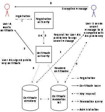
Figure 2‑1: Single certificate authority.
Figure
2‑1 also depicts the steps necessary when user A wants to
certify his or her private key with a certificate authority and how user B
obtains the respective public key for the encryption of a message to user A:
1) User A applies for a public
key certificate by the registration authority.
2) User A complies with the
registration authority’s policy and the registration authority allows the
certificate authority to issue the certificate.
3) The certificate authority
signs user A’s public key and issues the certificate to user A as well as
stores a copy in the certificate directory which is publicly accessible.
4) User B wants to send a
secret message to user A and needs to encrypt the message with user A’s
public key. User B gets the public key from the certificate directory.
5) User B queries the
certificate revocation list.
6) Only user A’s private
key can decrypt such a message encrypted by user A’s public key.
A major problem with public key certificates is that nobody
knows at first glance if they are still valid, revoked, or falsified. As in the
single certificate authority model only one certificate authority exists, the
process of verifying the actual state of a public key is relatively simple
because only one certificate revocation list has to be maintained and queried
by the users. Figure
2‑2 shows how user D may verify user C’s
certificate issued by certificate authority X:
1) User D queries the
certificate directory and the certificate revocation list of certificate
authority X to inquire if the certificate is still valid or revoked.
2) User D requests user
C’s certificate authority X’s public key which is publicly
accessible.
3) User D is now able verify
the signature on user C’s public key certificate and learns if user
C’s public key was issued by the certification authority X or not.
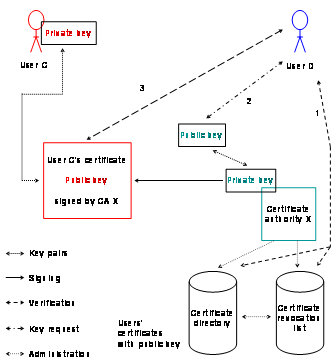
Figure 2‑2: Certificate lookup with one certificate authority.
Hierarchical Certificate Authorities
In the hierarchical certificate authorities’ model, one
root certificate authority signs the public keys of its sub certificate
authorities and not public keys from each user as in the single certificate
authority model. Each sub certificate authority can have one or more sub
certificate authorities. In that way, it is possible to generate tree like
structures with many sub certificate authorities. All certificate authorities
could also sign user certificates but normally only the leaves of the tree do
that. Figure
2‑3 shows the hierarchical model with one root
certificate authority and two sub certificate authorities. The private key of
the root certificate authority signs the public key certificates of certificate
authority 1 and 2. User A’s and user B’s public key certificates
are signed by their respective certificate authority. Everybody may validate
these users’ public key certificates with the public key of the root
certificate authority.
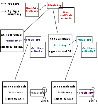
Figure 2‑3: Hierarchical certificate authorities.
Cross Certificate Authorities
In the real world, many root certification authorities exist
and certificate verification is a time consuming task impossible to execute for
the majority of users in the Internet. To ease certificate verifications, some
certificate authorities cross certify their root certificates.
The advantage of cross certification for users is that they can
assume certificates reliable if that certificate authority’s public key is
also signed by their own certificate authority. A certificate authority that
signs another certificate authority’s public key is the root certificate
authority and the other, the sub certificate authority. If a sub certificate
authority signs other certificate authorities’ public keys and those do
the same with other certificate authorities, they generate cross certification
chains.
Figure
2‑4 shows certificate authority 1 and 2 that cross
certify their certificates. Certificate authority 1 uses its root private key
to sign the root public key of certificate authority 2. The thereby signed
public key becomes now certificate authority 2’s public key certificate. Certificate
authority 2 does the same but vice versa. Certificate authority 1’s
public key can now be used to verify certificate authority 1’s issued
public key certificate but also to verify certificate authority 2’s
issued public key certificate and vice versa. User A’s key pair consists
of a private key and public key which is signed by certificate authority
1’s public key, resulting in user A’s public key certificate. The
same happens for user B with certificate authority 2. User A’s
certificate allows to User B to verify the validity of this certificate and
vice versa.
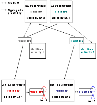
Figure 2‑4: Cross certification with two certificate
authorities.
All users may store trust worthy public key certificates in
applications, which possess the trust list feature. The acceptance and storage
of these certificates demands a certain understanding from users as well as the
ability to read the policy conditions, which can already be a problem due to an
unknown language. Applications featuring pre-configured trust lists containing
public key certificates of those root certificate authorities, which spent time
and money and conform to the policies for the list integration make the installation
procedure for end users obsolete.
Most web browsers, feature trust lists with pre-stored root
certificates from many different certificate authorities. Figure 2‑5 shows user, A which uses a web browser.
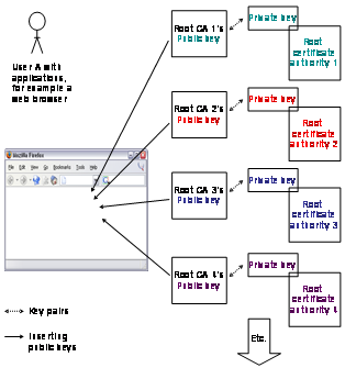
Figure 2‑5: Trust lists.
In this web browser, root certificate authorities 1 to 4 have
already inserted their root public keys. User A could remove unwanted keys of
the list or additionally add new keys. User A now opens a web site, which makes
use of encrypted data. The web site owner owns a public key certificate from
root certificate authority 2. User A may now validate this certificate by means
of the built in root certificate of certificate authority 2. If the web site owner
does not belong to a pre-added certificate authority, the user has to decide if
he or she wants to accept and install the new certificate and trust the new certificate
authority.
Public Key Infrastructure in Grid Computing
At least one of the global grid projects, the Grid Security
Infrastructure, uses the above-discussed PKI technologies for the data
transmission between its servers and clients. As discussed, in public key
infrastructures messages can be decrypted only with the respective private key.
This is a problem in the area of mass computing such as in the Grid area as
clients send calculation jobs to a network of linked computers unable to decrypt
the data because they do not have the users’ private key. To overcome
this problem, grid security infrastructure makes use of delegated proxies
acting on behalf of users and resources. A delegated proxy is a proxy acting on
behalf of the anterior proxy. Such proxies do not use the original long-lived
certificates but their own short-lived ones. The advantage of those self-signed
certificates lies in their short lifetime and the resulting loss of danger for
involved keys in automated processing. These proxies can communicate without
involving the real user. [NTW01] describes an implementation of such a proxy
chain in detail.
Evaluation of the Different Models
After the discussion of the different public key infrastructure
models, we discuss and evaluate their advantages and disadvantage, for the use
in the later discussed architectures.
Single Certificate Authority
It is an unrealistic assumption that one day, only one
certificate authority would exist worldwide, and that each user gets his or her
signed public key certificate directly from there. This root certificate
authority would have immense power and be able to control all certificate
holders. For an e-learning architecture, the single certificate authority model
is interesting in an isolated environment. It enables the operator of such an
environment to issue own certificates for server-to-server traffic and for the
users. Users would have to accept and import the server certificates in their
applications such as web browsers, the first time they get into contact with
encrypted data of this certificate authority. Certificate authorities often
issue the server certificates are over the Internet, an issuing process with a
potential for data interception by attackers.
Hierarchical Certificate Authority
The hierarchical certificate authority model delegates
responsibility to sub certificate authorities. All sub certificate authorities
have to comply with the policies of all their upper certificate authorities but
may issue policies that are more limited. The root certificate authority is
still very powerful. This model is interesting, if for example a country sets
up an official root certificate authority and organizations within this country
operate sub certificate authorities. The advantage over the single certificate
authority model lies in the delegation of reliability and administrational work
to a root certificate authority, which manages law and financial issues. Due to
the larger user community in the hierarchical model, the possibility that root
keys of such root certificate authorities find their way in applications such
as web browser is much higher than in the single certificate authority model. Another
advantage is that an organization may set up two certificate authorities with
different policies under the same root certificate authority, one for server
certificates, and another for user certificates.
Cross Certificate Authority
Cross certification is a useful workaround, which allows
relating certificate authorities of the single and hierarchical model and make
root certificates of one certificate authority accepted by more users. However
cross certification complexity increases with the number of partners. With each
joining certificate authority, it is more difficult to keep track of the
certificate network, especially if considering that certification chains can
intersect. In big cross-certified networks, reliability may easily get lost and
the advantages of public key infrastructures go along.
Applications with Trust Lists
Trust lists provide a high comfort to end users. Due to the
pre-added public keys to users’ applications such as web browsers, no
further user interaction is necessary when transferring encrypted data with the
resource servers. If root certificates are not integrated in users’
applications, users get used to accept certificates and skip warning messages.
A negative aspect is that users do not know most certificates in the trust
lists of their applications (e.g. in web browsers). Integration of root
certificates into applications is time consuming and expensive but alleviates
e-learning resource users from the task of certificate installations in their applications.
Comparison and Recommendations
The features of each of the three evaluated public key
infrastructures are condensed and compared in Table
2‑1. Features provided are marked as X, features provided
under certain conditions as (X).
|
|
Single |
Hierarchical
certificate authority |
Cross |
|
One root
certificate authority |
X |
X |
|
|
Several
root certificate authorities |
|
|
X |
|
One
registration policy |
X |
|
|
|
Several
registration policies |
|
X |
X |
|
One
certificate realm |
X |
|
|
|
Several
certificate realms |
|
X |
X |
|
Delegable
certificate realms |
|
X |
(X) |
|
Different
trust standards |
|
(X) |
X |
|
Provides
full authority to resource owners in whole certificate realm |
X |
|
|
|
Provides
full authority to resource owners in own certificate realm |
|
X |
|
|
Single and
hierarchical certificate authorities linkable without loosing independency |
|
|
X |
|
Useful if
server to server traffic is encrypted as no user applications have to be
adapted |
X |
X |
X |
|
Lower
costs for certificate integration in user applications |
|
X |
(X) |
|
One
certificate revocation list |
X |
|
|
|
Several
certificate revocation lists |
|
X |
X |
Table 2‑1: Comparison of PKI models.
Evaluation recommendation:
We do not recommend using a single certificate authority for
server-to-server traffic encryption and no end user applications can get into
contact with the issued certificates without having to install the certificates
manually or without spending a high amount of money for the certificate
integration into applications such as web browsers. We recommend using a
hierarchical certificate authority model in the role of a sub certificate authority
with control over its own certificate realm. The costs for the integration of
root certificates in user applications should be lower than in the single
certificate model due to the larger user community participating in the costs.
Cross-certified certificate authorities are interesting enhancements to the
single and hierarchical certificate authority models. However, cross certifying
many certificate authorities results in a loss of trustworthiness in the trust
network. We recommend using end user applications with trust lists in any case
with traffic between end users and servers.
2.2.2 Authentication with Kerberos
The Massachusetts Institute of Technology (MIT) developed
Kerberos [CT94]. The name Kerberos originates from Greek mythology, where Kerberos
is the name of the three-headed dog that guards the entrance to Hades. Kerberos
is a network authentication protocol, designed to provide strong authentication
for client/server applications by using secret key cryptography. Secret key
cryptography is a synonym for symmetric key cryptography and thus in secret key
cryptography, the same key serves to encrypt and decrypt data, in contrast to
public key cryptography, where a public and a secret key are necessary. In
Kerberos, client and server applications must be Kerberos enabled. The main
components in Kerberos are the Authentication Server (AS) and the Ticket
Granting Server (TGS). These servers together with a database form a Key
Distribution Center (KDC). Kerberos bases on keys for user authentication (kU)
and resource access (kR) as shown in Figure 2‑6. All resources together with the key distribution
center form a Kerberos realm. Up to Kerberos version 4, it was necessary to
establish a shared secret between all involved parties. This limited the
inter-realm connectivity as it was hardly possible to establish the same shared
secret over multiple realms, especially due to security risks in the case of
corruption of the shared secret. From version 5 on, Kerberos is more scalable
because it is possible to arrange hierarchically different Kerberos realms.
Each of these realms has its own authentication server and ticket-granting
server. It is also possible to use public key cryptography additionally to the
shared secret of the secret key cryptography.
Figure
2‑6 shows the involved parties in a Kerberos system. Both, the user and the service on the resource are required to
have keys registered with the authentication server. The user U that is located
at his or her computer wants to access the Kerberos protected resource R:
1) The user logs-in to the
computer and provides his or her user name and password together with his or
her key U (kU) for authentication with the authentication server.
2) The Kerberos client
installed on the computer sends a request for these credentials to the
authentication server. The request is contains the user name U to be
authenticated, the current time, the desired expiration time of the
authentication ticket and a random number.
3) The authentication server
checks if U is in its database and if it is the server sends back to messages
to the client: message A contains the client/ticket-granting server session
key. This message is encrypted with the secret kU of the user.
Message B contains the client identity, the client’s network address, the
ticket expiration time a random number and the client/ticket-granting ticket
session key. This message is encrypted with the secret key of the
ticket-granting server. Another name is Ticket Granting Ticket (TGT).
4) The client now decrypts message
A and with the client/ticket granting ticket session key, the user can now
request a ticket from the ticket-granting server with two messages. Message C
contains message B and the identity of the resource R. Message D contains the
client’s identity, and a timestamp. This message is encrypted with the
client/ticket granting ticket session key. The client itself cannot decrypt
message B, which is encrypted with the ticket granting servers’ secret
key.
5) Upon receiving messages C
and , the ticket granting server decrypts message D with the client/ticket
granting server session key and sends two messages to the client: message E
contains the client’s identity, the client’s network address, the
ticket expiration date and a client/resource session key, encrypted with the
resource’s secret key kR. Message F contains the
client/resource session key, encrypted with the client/ticket granting server
session key.
6) The client sends these
credentials to the resource R for accessing the requested service. Message G contains
message E and is encrypted with the resource’s secret key. Message H
contains message D, encrypted with the client/resource’s session key. The
resource now receives and decrypts the messages with its own kR and
the service provisioning starts.
7) The resource signals back
its decision to the
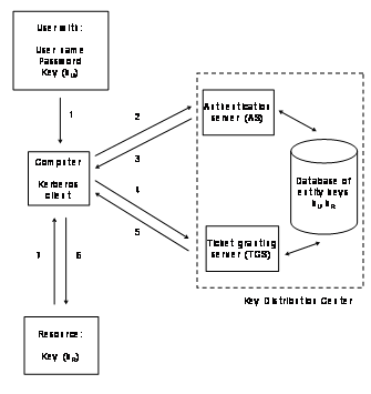
Figure 2‑6: Kerberos authentication.
Figure
2‑7 shows a user of Kerberos realm A accessing a resource
in Kerberos realm B. The user has keys registered with the authentication
server of realm A, the resource with the authentication server of realm B. The
user of realm A accesses the computer and wants to access the Kerberos
protected resource:
1) The user logs-in to the
computer and provides his or her user name and password together with his or
her key U (kU) for authentication with the authentication server of
his or her Kerberos realm A.
2) The Kerberos client
installed on the computer sends a request for these credentials to the
authentication server of realm A. The request is contains the user name U to be
authenticated, the current time, the desired expiration time of the
authentication ticket and a random number.
3) The authentication server
checks if U is in its database and if it is the server sends back to messages
to the client: message A contains the client/ticket-granting server session key
and also the key distribution center URL of realm B. This message is encrypted
with the secret kU of the user. Message B contains the client identity,
the client’s network address, the ticket expiration time a random number
and the client/ticket-granting ticket session key. This message is encrypted
with the secret key of the ticket-granting server. Another name is Ticket
Granting Ticket (TGT).
4) The Kerberos client
installed on the computer this time sends an authentication request for the user
to the authentication server of realm B, together with the credentials of realm
A, consisting of the decrypted message A. With the client/ticket granting
ticket session key, the user can now request a ticket from the ticket-granting
server with two messages. Message C contains message B and the identity of the
resource R. Message D contains the client’s identity, and a timestamp.
This message is encrypted with the client/ticket granting ticket session key.
The client itself cannot decrypt message B, which is encrypted with the ticket
granting servers’ secret key.
5) Upon receiving messages C
and , the ticket granting server of realm B decrypts message D with the
client/ticket granting server session key and sends two messages to the client:
message E contains the client’s identity, the client’s network
address, the ticket expiration date and a client/resource session key,
encrypted with the resource’s secret key kR. Message F
contains the client/resource session key, encrypted with the client/ticket
granting server session key.
6) These credentials can be
sent to the resource for accessing the requested service in the other Kerberos
realm. The resource now receives the ticket and the service accepts or rejects
the ticket.
7) The client sends these
credentials to the resource R for accessing the requested service in the other
Kerberos realm. Message G contains message E and is encrypted with the
resource’s secret key. Message H contains message D, encrypted with the
client/resource’s session key. The resource now receives and decrypts the
messages with its own kR and the service provisioning starts.
8) The resource signals back
its decision to the
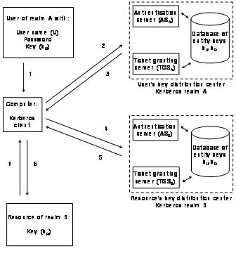
Figure 2‑7: Kerberos inter-realm connectivity.
Evaluation of Kerberos
Kerberos is a widely deployed authentication infrastructure but
not an authorization infrastructure. Client software for the most used applications
and server software exist for Microsoft Windows, Linux, and UNIX operating
systems. Only resources with many users such as commercial course platform [GSS96
and GS97] for example are Kerberos enabled. Smaller resources are not Kerberos
enabled. Even with the improvements realized in Kerberos version 5, some
limitations remain and an inter-realm shared secret or a public key
infrastructure certification are necessary. Inter-realm connections may result
in long certification chains, as an accessed resource in a foreign realm has to
trace back the user’s realm via the next realms in between. Therefore, Kerberos
does not scale for large user groups, which do not belong to a limited number
of organizations. A disadvantage of Kerberos is that it is not designed for
user authorization. It is only indirectly possible to authorize users. The only
possibility to authorize users in Kerberos is by issuing authentication
tickets, related to access rights defined in additional databases. This kind of
authorization causes high administrational overhead, because each user’s
authorization state, based on these additional authentication ticket has to be
stored in a database belonging to the e-learning courses resource management
system. Nowadays, it is easier to handle user authorization if it bases on user
information attributes.
User information Attribute
An attribute is a property of something. There exists
pre-defined attributes with corresponding values. A user information attribute
for a user name is such a pre-defined attribute in conjunction with the
respective user value.
Table
2‑2 lists the advantages and disadvantages found in
Kerberos:
|
Advantages |
Disadvantages |
|
·
Secure authentication
infrastructure. ·
Broadly deployed. ·
Natively supported in
Microsoft operating systems Windows 2000 and XP. ·
Supported in UNIX
derivatives. |
·
Pure authentication
infrastructure, authorization must be based on authenticated identities. ·
Inter-realm resource
access is complicated to realize. ·
Only organizations, which
operate a key distribution center for their users can participate |
Table 2‑2: Advantages and disadvantages of Kerberos.
Evaluation recommendation: We do not recommend using
Kerberos for the below described portal and e-learning architectures. Kerberos
is principally an authentication infrastructure and misses the authorization
part, important for e-learning resources such as the computer networks
laboratory. Kerberos especially lacks the feature of user authorization based on
user information attributes.
2.3.1 Internet Protocol Security
Internet Protocol Security
(IPSec) [SBDG02] is a technology for securing data transport between servers as
well as between servers and users in the Internet on IP level. This makes IPSec
an interesting potential technology to for securing traffic in e-learning architectures.
Furthermore, IPSec is the main topic of one of the below presented e-learning
module implementations in the computer networks laboratory. We therefore
discuss IPSec in detail. The Internet Engineering Task Force (IETF) standardized
IP version 6 (IPv6) [DH98 and Bt99] to solve pending problems such as address
shortage of the current version of the IP protocol (IPv4). A spin-off
development of this process was the IP security architecture, which introduces
per-packet security features. While delays in the IP version 6 deployment occurred,
the security architecture was adapted to the current IP version (IPv4). A key
motivation for this adaptation was that Internet protocol security comprises
all security mechanisms needed to implement a Virtual Private Network (VPN).
Virtual private network
A virtual private network is an encrypted data link, allowing
the use of public networks for sending private data.
The Internet security
architecture comprises of a family of protocols. IPSec describes IP packet
header extensions and packet trailers, which provide security functions. We present
the Authentication Header (AH), Encapsulating Security Payload (ESP), Security
Associations (SA), and Internet Key Exchange (IKE) in more detail. The
per-packet security functions originate from two protocols: The authentication
header [KA98a], which provides packet integrity and authenticity and the
encapsulating security payload [KA98b], which provides privacy through
encryption. Authentication header and encapsulating security payload are independent
protocols, applicable separately or combined. A reason for the separation of
the security mechanisms was that there exist countries with restrictive regulations
for encrypted communication. In such countries, IPSec can be deployed solely
using authentication header because authentication mechanisms are free unlike
payload encryption. The set of authentication header and encapsulating security
payload is also required in order to guarantee interoperability between
different IPSec implementations. Both protocols’ specifications do not
include cryptographic algorithms. Hence, it is simple to add a new encryption
algorithm to IPSec. Both authentication header and encapsulating security
payload assume the presence of an encryption key known to the involved parties.
This key may be installed manually. A better and more scalable approach is to
use the third protocol of the IPSec family: the Internet key exchange protocol
[HC98].
Security Association and Security Policy Database
At some point in the
network, both authentication header and encapsulating security payload
protocols perform a transformation to IP packets. The IPSec compliant nodes
always form sender/receiver pairs where the sender performs the transformation
and the receiver reverses it. The security
association describes the relation between sender and receiver. Nota
bene that the security association describes just one transformation and its
inverse. Concatenated security associations describe concatenated
authentication header and encapsulating security payload transformations.
Security associations may be seen as descriptions of established IPSec
connections. Both IPSec peering machines store representations of security
associations. An IPSec security association specifies important settings:
- The mode of the
authentication algorithm used in the authentication header and the
respective keys.
- The encapsulating
security payload encryption algorithm mode plus the respective keys.
- The presence or
absence of any cryptographic key synchronization used to determine the
identical transaction key used in the selected encryption algorithm.
- The frequency for the
exchange of those keys.
- The authentication
algorithm and authentication mode applied in encapsulating security
payload plus the respective keys.
- The key’s
lifetime.
- The own lifetime.
- The source address.
- The sensitivity level
descriptor, a security level indicator.
A security association is uniquely identified by a triple
consisting of a Security Parameter
Index (SPI) (a 32-bit number), the destination IP address, and
the IPSec protocol in use (authentication header or encapsulating security
payload). The sending party writes the security parameter index into the
appropriate field of the IP protocol extension. The receiver uses this
information to identify the correct security association. The receiver is able
to invert the transformation and to restore the original packet. Each IPSec
compliant machine may be involved in an arbitrary number of security associations.
Accordingly, a security
association is a management construct used to enforce a security policy in the
IPSec environment. The policy specifications are stored locally in every IPSec
node’s Security Policy Database (SPD), consulted each time when processing
inbound and outbound IP traffic, including non-IPSec traffic. The security
policy database contains different entries for inbound and outbound traffic.
The security policy database determines if traffic must be encrypted or can
remain as clear text, or if traffic must be discarded. If traffic is encrypted,
the security policy database must point to the respective security association
by a selector, a set of IP and upper layer protocol field values to map traffic
to a policy.
Transport and Tunnel Mode
Both, encapsulating security payload and authentication header
have two modes: the transport mode and the tunnel mode. In the transport mode,
only the payload and a part of the IP header get encrypted and authenticated.
It extends the IP headers by adding additional fields. The original IP header
remains the same before and after encryption. Figure
2‑8 shows an IP packet after applying the authentication
header protocol. The authentication header adds information between the
original IP header and the TCP/UDP/ICMP header. Figure 2‑9 shows an IP packet after applying the encapsulating
security payload protocol. After the original IP header, the encapsulating
security payload header is inserted and at the tail, an encapsulating security
payload trailer 1and an encapsulating security payload authentication are
added.

Figure 2‑8: IP packet after applying AH in transport
mode.

Figure 2‑9: IP packet after applying ESP in transport mode.
The tunnel mode is ideal
for implementing a virtual private network tunnel between Internet access
routers as access routers can be equipped with special hardware, which encrypts
and decrypts data faster than end systems without the respective hardware.
Equipping many end systems with this type of hardware is more expensive than
equipping few access routers. Figure
2‑10 shows an IP packet after applying the encapsulating
security payload protocol in tunnel mode. The packet begins with a new IP
header containing the addresses of the IPSec tunnel end points followed by an
encapsulating security payload header. Then, the original IP packet follows and
at the tail, an encapsulating security payload trailer and an encapsulating
security payload authentication added.

Figure 2‑10: IP packet after applying ESP in tunnel
mode.
The new IP header may be
secured using authentication header. The tunnel mode allows passing
non-routable IP addresses or other network protocols through a public network
as the addresses of the inner header are hidden. Hiding the original network
topology also provides privacy.
The Internet Key Exchange Protocol
If two parties would like to communicate using IPSec, they need
to negotiate the parameters in the security association. If the parameters have
to be established manually, the process is time consuming and assumes that the
involved parties possess required knowledge. The Internet key exchange protocol
allows two nodes to automatically and securely set up and renew the required
security associations. Internet key exchange uses the Internet Security
Association and Key Management Protocol (ISAKMP) [MSST98] to exchange messages.
The Internet security association and key management protocol provides a
framework for authentication and key exchange but does not define a particular
key exchange scheme. Internet key exchange uses parts of the two key exchange
schemes Oakley [Oh98] and Secure Key Exchange Mechanism (SKEME) [Kf96].
Internet key exchange
operates in two phases. In phase 1, the two peers establish a secure
authenticated communication channel (also called ISAKMP security association).
In phase 2, security associations can be established on behalf of other
services (most prominently IPSec security associations). Phase 2 exchanges require
an existing Internet security association and key management protocol security
association. One Internet security association and key management protocol
security association can protect several phase 2 exchanges and a phase 2
exchange can negotiate several security associations on behalf of other
services. The Internet security association and key management protocol
security association is bi-directional and the following attributes are used by
Internet key exchange and negotiated as part of the Internet security
association and key management protocol security association: encryption
algorithm, hash algorithm, authentication method, and initial parameters for
the Diffie-Hellman algorithm [Sb96].
2.3.2 Secure
Sockets Layer and Transport Layer
Security
The Secure Sockets Layer Protocol (SSL) developed by Netscape [FKK96]
or the standardized version Transport Layer Security (TLS) [DA99] are designed
to provide privacy and data integrity between two communicating applications
(i.e. a client and a server) by using public key cryptography as described in Chapter
2.2.1 for example together with RSA or DSS [RSA78 and
GJKR96]. TLS 1.0 and SSL 3.0 do not interoperate although TLS is an enhancement
of SSL [Ra00]. The protocols are also designed to authenticate the server, and
optionally the client. SSL/TLS require a reliable transport protocol (e.g. TCP
[Pj81]) for data transport.
One advantage of SSL/TLS protocols is that it is application
protocol independent. This makes secure sockets layer a base technology for
applications used in the e-learning architecture. An application level
protocol, such as the Hypertext Transfer Protocol (HTTP) [FGMF99], the File
Transfer Protocol (FTP) [PR85], and Telnet [PR83] can layer on top of the
SSL/TLS protocols transparently as shown in Figure
2‑11. SSL/TLS protocols can negotiate an encryption
algorithm and a session key as well as authenticate a server before the
application protocol transmits or receives its first byte of data. SSL/TLS
support the use of X.509 digital certificates from the server so that, if
necessary, a user can authenticate the sender.
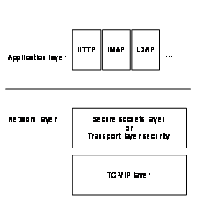
Figure 2‑11: SSL/TLS principle.
All application protocol data is encrypted before
transportation, be it HTTP, Internet Message Access Protocol (IMAP) [LLM97],
Lightweight Directory Access Protocol (LDAP) [YHK95] or others thereby ensuring
privacy. Connections provided by SSL/TLS protocols are private, authenticated,
and reliable. All messages are encrypted using secret key cryptography for
example with DES, 3DES or RC4 [DES, Tw79, TK97] with a session key that is
defined at the beginning with an initial handshake. A session key is a cryptographic
key valid only for one communication session. The server endpoint of the conversation
is always authenticated, while the client endpoint authentication is
optionally. The protocol includes a message integrity check using a Message
Authentication Code (MAC) for detecting packet alteration between client and
server. The MAC is calculated using secure one-way hash functions for example
with SHA or MD5 [SHA, Rr92].
The Secure tunnel or Stunnel [VMC02] is an application, which
uses secure sockets layer to encrypt and tunnel TCP connection between the IP ports
of two networked computers. Doing so, non-secure sockets layer aware
applications’ traffic can be encrypted without changing their program
code. A Stunnel server provides two functionalities: First, it receives
unencrypted traffic, encrypts the traffic, and sends it to the Stunnel client
over the Internet. Secondly, it receives encrypted traffic, decrypts the
traffic, and then sends it over the Internet to another program residing on the
same computer. Stunnel may be used for encrypting server-to-server traffic in
the e-learning architecture.
Hypertext Transfer Protocol over Secure Sockets Layer
Hypertext Transfer Protocol over Secure Sockets Layer (HTTPS)
or HTTP over SSL [BFF96] is used for encrypted transport of web pages over
secure sockets layer. Most web browsers (Netscape, Explorer, Mozilla, Opera,
Safari, etc.) support HTTPS without any additional software installation on the
client side. HTTPS encrypts and decrypts user page requests and the returned
pages. HTTPS connections are often used for submitting private information such
as credit-card numbers and personal details. Web servers such as Apache and
Microsoft Internet Information Server can be equipped with SSL/TLS modules.
HTTPS may be used for a secured transport of web pages of the e-learning architecture.
During a long time, Telnet served for remote access to
computers. Although still in use, it is no longer popular due to its
unencrypted data transport. In addition, user name and password pass Internet
in clear text. The Telnet successor’s name is Secure Shell (SSH) [Yt96].
SSH provides secure login, file transfer, and TCP/IP connections over a public
insecure network such as the Internet. It uses cryptographic authentication,
automatic session encryption, and integrity protection for transferred data.
The available SSH clients provide least the same functionalities as Telnet
does. SSH supports the use of public key cryptography. SSH may be used for the
client connection to the resource servers and laboratory devices of the e-learning
architecture.
2.3.4 Evaluation of the Different Transport Technologies
Evaluation of Internet Protocol Security
IPSec is a potential candidate for the encryption of
server-to-server traffic. Unfortunately, the implementations of the Internet
key exchange protocol is not so advanced as necessary to use it for server to
end system encryption and most IPSec tunnels must be set up manually. This is a
major disadvantage as nobody can expect users to set up complicated tunnel
configurations before attending an e-learning resource. IPSec is the choice for
securely transporting traffic from whole sub networks behind access routers to
other network areas.
Evaluation of Secure Sockets Layer
SSL/TLS is an option for securing the network traffic from
different applications. SSL/TLS is able to encrypt the traffic between servers
and servers and clients. An advantage of SSL/TSL is that public key
infrastructures may be used for issuing encryption keys. Particularly
applications with pre-configured trust lists in combination with root certificate
authorities, which have stored their root certificates in these trust lists,
facilitate the user access to the e-learning resources.
Stunnel bases on SSL/TLS and provides a safe data transport
over public wires. It is an encryption technology, which is deployable within
minutes and provides the advantage of tunneling traffic from unmodified
applications’ IP number port to IP number port.
HTTPS bases on SSL/TLS and supported by most existing web
browsers. It is user-friendly, as users do not have to install additional
software to retrieve and send encrypted web pages.
Evaluation of Secure Shell
Secure shell is an application for directly connecting clients
to hosts and having the same working environment as with a Telnet shell. The
advantage of secure shell is that it encrypts all the traffic. It is possible
to use a public key infrastructure for issuing encryption keys. Secure shell
implementations exist in many variations, also as Java applets. It is essential
for a computer networks laboratory that students can connect to the laboratory
devices such as routers and hosts in the same way they would do this locally.
Secure shell provides this possibility. The existing Java version additionally
fulfills the requirement of no additional software installation on client side.
Comparison and Recommendations
The features of each of the three evaluated secure data
transport technologies are condensed and compared in Table 2‑3. Features provided are marked as X, features provided
under certain conditions as (X).
|
|
IP
security |
SSL/TLS |
Secure
shell |
|
Standardized
protocols |
X |
X |
X |
|
Tunnels
data traffic from IP number to IP number |
X |
|
|
|
Tunnels
data traffic from IP number port to IP number port |
|
X |
X |
|
Use of PKI
issued keys possible |
X |
X |
X |
|
End user
friendly set up |
(X) |
X |
X |
|
Available
for most operating systems |
X |
X |
X |
|
Widely
deployed |
X |
X |
X |
|
If public
key certificate is not pre- stored to the trust lists of the applications, users
have first to accept/import the certificate. |
|
X |
(X) |
Table 2‑3: Comparison of Transport Technologies.
Evaluation recommendation:
We recommend using IP security protocols for the encryption of
the server-to-server traffic in the e-learning architecture as the complexity
for the set up of these connections can be justified by the high security level
achieved. For non-static server IP numbers or in the case simpler set up
procedures and less security is necessary, we recommend using an SSL/TLS based
encryption method such as Stunnel. We recommend using the SSL/TLS based HTTPS
encryption for the web page transport between resource servers and students,
tutors and administrators. We recommend using SSH for the encrypted data transfer
between resources of the e-learning architecture, which exceed shell access,
such as the laboratory devices of the computer networks laboratory.
2.4
Authentication and Authorization
Infrastructures
This Chapter starts with the discussion of the lightweight
directory access protocol, the authentication and authorization infrastructure,
which builds the base of the resource management system in both of the
multifunctional e-learning architectures. Subsequently we discuss Shibboleth,
the authentication and authorization infrastructure chosen by the Swiss
universities [Gc03]. Although Shibboleth is the pre-selected architecture for
the Swiss universities and the prototypical implementation of the e-learning computer
networks laboratory belongs to a Swiss university, we discuss, evaluate, and
compare potential competitors. After Shibboleth, we discuss another interesting
authentication and authorization infrastructure with similarities to
Shibboleth, the Spanish authentication and authorization infrastructure PAPI.
We then discuss the remote authentication dial-in user service RADIUS and
Diameter, its further development. We also discuss the Liberty Alliance
project, a standardization alliance, which intends to group existing standards
and protocols together and to provide a single sign-on system similar to
Shibboleth, but with accounting and charging in mind. We also discuss the Microsoft
passport project, the trigger for the formation of the liberty alliance. We conclude
this sub Chapter with a comparison of all the infrastructures and
recommendations for their use in our architectures.
2.4.1 Lightweight Directory Access Protocol
In Chapters 4 and 5, we describe a multifunctional e-learning architecture
and its extended version. The preconditions to a technology for the
implementation of such architecture are integrated authentication and
authorization mechanisms, as well as the possibility to use it for laboratory
device reservations. We have chosen the lightweight directory access protocol,
because it fulfills these preconditions. LDAP is also extendable in several
directions, it allows, for example, to use standardized user information attributes
but also to define own user information attributes. Furthermore, it is possible
to subordinate an architecture based on the lightweight directory access
protocol to other authentication and authorization infrastructures. In this
Chapter, we discuss the technical features of the lightweight directory access
protocol, optimized for fast read access to databases for clients, such as the
geographically distributed laboratories of the computer networks laboratory.
These laboratories connect to the Internet with laboratory portals, which act
as brokers between the laboratory devices and the users as well as the resource
management system. The laboratory portals frequently read out the reservation
status of the hands-on trainings in the database, whereas user account changes
and bookings in the database occur less frequently. Initially, the design of
the lightweight directory access protocol described how clients access X.500
directories, without incorporating all the functionalities of the Directory
Access Protocol (DAP). In the meantime, the further developed lightweight
directory access protocol is a client/server protocol for accessing existing
X.500 directories but also a standalone directory server. Because of the further
development, there exist LDAP clients and LDAP servers now. LDAP clients send a
protocol request, which describes the requested operation on the server. LDAP
servers function as a replacement of the X.500 servers and are responsible for
performing the necessary operations on the directory database. Upon completion
of the necessary operations, the server provides the directory information to
the clients.
Attribute Types and Object Classes
In X.500 and LDAP directories, information is stored as values
related to attributes, i.e. attribute/value pairs. The same syntax of
attribute-value pairs is also valid for X.509 certificates, where the same
standardized attributes are used. Each dataset in an LDAP directory starts with
the attribute distinguished name (dn), which can be considered as the most
important attribute at all.
A distinguished name uniquely
identifies an entry within the hierarchical directory. The dn consists of the
entry's name plus the path (list of entry names) back to the top of the tree. Figure 2‑12 shows the principle of an LDAP tree with some
attributes taken from Table 2‑4. There is always an origin at the bottom of the
trunk. Each distinguished name starts at a leave, going back from branch to
branch until reaching the trunk.
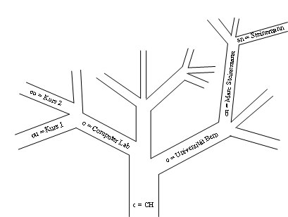
Figure 2‑12: LDAP tree.
Each dn must be unique and can only exist once in an LDAP
directory. A dn is the key to find its corresponding entry within the tree-like
directory structure. From right to left, a dn contains all the entry's names
leading from the top level to the desired entry. The dn
dn:
sn=Steinemann,cn=Marc Steinemann,o=Universität Bern,c=CH
means that the person Marc Steinemann with the surname Marc
belongs to the
|
Attribute |
Meaning |
|
c |
country |
|
dn |
distinguished
name |
|
cn |
common
name |
|
sn |
surname |
|
o |
organization |
|
ou |
organizational
unit |
Table 2‑4: Set of standardized LDAP attributes.
Attribute types more precisely specify attribute/value pairs. An attribute type defines the data
representation format and the order of the associated values. Additionally, an
attribute type allows specifying whether an attribute consists of one single
value or of a set of values. An object class specifies a collection of
attributes. An object class specifies the collection of attributes available to
specify a data set. There are two groups of attributes. The first group
specifies required attributes in order to specify a valid data set; the second
group lists additional attributes, which can characterize the data set. A data
set can belong to more than one object class if it provides all the required
attributers specified in the concerned object classes. Data sets must belong to
at least one object class.
Schema Files
The different available object classes and attribute types are
stored in schema files. There exist standard schema files like core.schema that
defines the LDAP schema items specified in RFC 2251 – 2256 and
cosine.schema describes items specified in RFC 1274. These essential schema
files include the most common object classes and attributes. The specification
for the attribute name looks as Figure
2‑13 shows:
attributetype ( 1.3.6.1.4.1.3536.2.7.1.4 NAME 'hostname'DESC 'Hostname of the machine where the file is stored' EQUALITY caseIgnoreMatch ORDERING caseIgnoreOrderingMatch SUBSTR caseIgnoreSubstringsMatchSYNTAX 1.3.6.1.4.1.1466.115.121.1.26 )
Figure 2‑13: Attribute definition schema.
The attribute is specified by a unique number expressed as a number
in the Abstract Syntax Notification number 1 (ASN.1) code [TNF97] and the
attribute’s name. The parameter DESC describes the abstract number in a
human understandable form. EQUALITY specifies if the attribute is case
sensitive or insensitive. This is a quite important decision, especially for a
directory where persons frequently search for names and do not want to repeat
each search with all possible writings of the name. ORDERING specifies if the attribute
values have to obey a certain order and SUBSTR specifies if the substrings of
the attribute are case sensitive. SYNTAX specifies the type of value.
Figure
2‑14 shows the specification for the object class globus
(this is not a real existing object class):
objectclass ( 1.3.6.1.4.1.10434.99.97.111 NAME 'globus' DESC 'describes the Globus' SUP top STRUCTURAL MUST sn $ cn ) MAY o $ ou $ c
Figure 2‑14: Object class definition schema.
Each specified object class is defined by an ASN.1 number
followed by the parameter NAME and the name of the object class. SUP specifies
the parent object class from which the current object class inherits
specifications. STRUCTURAL prevents a dataset to belong to more than one structural
object class. It helps for example, to prevent that a dataset can represent a
person and an organization at the same time. MUST specifies the attributes a
dataset must contain and MAY specifies the attributes a dataset may contain.
Importing and Modifying Data
Principally, we can enter LDAP data in two ways: The first is
to enter the data in the command line, each by each. The second is to write an
LDAP import file (ldif). There exist tools with graphical user interfaces,
which use the first method to add, modify, and delete data.
An ldif file to add a dataset for Marc Steinemann at
dn: c=CH
objectclass: top
objectclass: country
c: CH
dn: o=Universität Bern,c=CH
objectclass: organization
o: Universität Bern
dn: cn=Marc
Steinemann,o=Universität Bern,c=CH
objectclass: person
cn: Marc Steinemann
sn: Steinemann
Figure 2‑15: Example ldif file.
Aliasing
It is possible to alias already existing directory entries to
other locations in the directory. The advantage of aliasing entries lies in the
fact that the data update process is much easier because only one copy of a
data set exists.
dn: cn=Marc
Steinemann,ou=IAM,o=Universität Bern,c=CH
objectclass: alias
aliasedobjectname: cn=Marc Steinemann,ou=RVS,o=Universität
Bern,c=CH
Figure 2‑16: Alias entry.
Figure
2‑16 shows an alias entry for Marc Steinemann who works at
the department IAM in the
Referring
LDAP gives the possibility to refer to other LDAP directories. With
such referrals, it is possible to include directory branches of one server into
the directory tree of another server. The sub tree of the second server refers
with a link in the root server (i.e. the server that is linking to the other
server). The functionality of a referral is similar to the one of an alias with
the difference that it does not link within a directory but between
directories.
Figure
2‑17 shows two datasets in two different directory
servers, each for an own branch of the same organization:
dn: o=Universität Bern,c=CH
objectclass: organization
o: Universitä Bern
dn: ou=FirstFloor,o=Universität Bern,c=CH
objectclass: organizationalunit
ou: FirstFloor
dn: cn=Marc Steinemann,ou=Phil. Nat,o=Univesität Bern,c=CH
objectclass: person
cn: Marc Steinemann
sn: Steinemann
dn: o=Universität Bern,c=CH
objectclass: organization
o: UniversitätBern
dn: ou=ThirdFloor,o=Universität Bern,c=CH
objectclass: organizationalunit
ou: ThirdFloor
dn: cn=Attila Weyland,ou=Phil. Nat,o=Univesität Bern,c=CH
objectclass: person
cn: Attila Weyland
sn: Weyland
Figure 2‑17: Two directories for two branches.
Figure
2‑18 shows the necessary entry in the directory server of
the branch FirstFloor to include (refer) the directory sub tree of branch
ThirdFloor into its own:
dn:
ou=ThirdFloor,o=Universität Bern,c=CH
objectclass: referral
objectclass: extesibleobject
ref:
ldaps://ldaps.thirdfloor.universityofbern.ch/ou=ThirdFloor,o=UniversityOfBern,c=CH
Figure 2‑18: Referral entry.
The referral entry contains the object class’s referral
and extensible object. The attribute ref contains the URL of the referred
directory and the distinguished name of the branch to be included. Figure 2‑19 shows an example of a referral lookup. A user enters
a search string into the LDAP client, which starts the database lookup in the
LDAP server A. The server A has a referral configured and thus links a branch
of LDAP server B into its own tree. In this way, server A returns the entry
found in LDAP server B to the client.
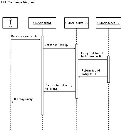
Figure 2‑19: UML sequence diagram for a referral
lookup.
Evaluation of the Lightweight Directory Access Protocol
LDAP directory servers exist as open source implementations and
may be used for combinations of user and device management functions. With
LDAPS exists a secure sockets layer enhanced implementation for encrypted data
transport over the Internet. LDAP provides the possibility to operate
distributed laboratory portals and resource content servers as well as
authentication and authorization of students, tutors, and administrators. Few
user account changes and reservation actions take place but many read outs from
laboratory portals and resource content servers. LDAP does not scale in cases with
multiple linked LDAP directories, as the access policy is set up per data entry
and directory, resulting in a high administrational overhead. LDAP directories
are adaptable to receive user database entries from other user databases, such
as for example from our institution’s user databases or other
authentication and authorization infrastructures, called root infrastructure. A
root infrastructure is hierarchically on top of the sub or subordinate
infrastructure. For example, a countrywide authentication infrastructure acts
as the root infrastructure if it adds user accounts to another authentication
infrastructure, for example belonging to one of several universities within the
country. The terms root and sub have an identical meaning as in the context of
public key infrastructures. Consequently, a multifunctional e-learning
architecture based on LDAP could become a subordinate system in the framework
of a broadly deployed user management system. Table
2‑5 lists the advantages and disadvantages of LDAP:
|
Advantages |
Disadvantages |
|
·
Standardized protocol. ·
Broadly deployed. ·
Fits the preconditions
for an environment with distributed content providing servers. ·
Possible to integrate a
public key infrastructure. ·
Fast readouts optimized
database is. ·
LDAP is available as
LDAPS, a version that uses SSL-encrypted data transport. ·
Possible to realize a
laboratory device reservation system. ·
Possible to refer LDAP
directories. ·
Root directories can feed
an LDAP directory. |
·
The access policy
definitions for referred LDAP directories are very complicated and hardly
manageable in the case of a large directory. |
Table 2‑5: Advantages and disadvantages of LDAP.
Evaluation recommendation: As already anticipated in
the introduction, we recommend using LDAP for the multifunctional e-learning
architecture discussed in Chapter 4 and the extended version in Chapter 5, because authentication, authorization and device reservation
functions can be realized, together with the possibility to define user information
attributes and to subordinate LDAP to other authentication and authorization
infrastructures.
The name of Internet2’s authentication and authorization
infrastructure initiative is project Shibboleth [Shibboleth and CE02]. The term
Shibboleth originates from Hebrew. It served to differentiate group members
from non-group members by a word, phrase, or habit, only known to querying
group. Shibboleth is an authentication and authorization infrastructure
architecture for web-based services. Shibboleth is a joint project of Internet2
and the Middleware Architecture Committee for Education (MACE). It aims to develop
an architecture for a standards-based vendor-independent web access control infrastructure,
which can operate across institutional boundaries. Shibboleth targets at educational
use without integrating charging and accounting schemes. Shibboleth provides single
sign-on functionality without providing a single log-out mechanism. Shibboleth
specifications and software for target site (resource) as well as origin sites (home
organization) is freely available. Shibboleth allows federated user
administration. In federated user administration, it is possible to delegate the
user management to the users’ home organizations, residing in different
administrational areas, which administrate and maintain a database with their
own users and participate in the authentication and authorization
infrastructure. Shibboleth also provides resource access based on user information
attributes and active privacy management for users. It uses the simple object
access protocol and the security assertion markup language for the message and
assertion formats as well as for the protocol bindings. We now define regularly
used terms:
Assertion
The term assertion in computer sciences defines a declaration
about a specific user or object.
Federation
A federation in the context of authentication and authorization
infrastructures is a union of autonomous organizations, agreeing in technical
and legal aspects to enable user information exchange within the federation and
sometimes within different federations also.
Handle
A handle in computer sciences is a unique sequence of data used
to identify a certain action or transaction.
Opaque
The adjective opaque describes an object whose content is not
visible, be it through an intransparent surface or through encryption.
SOAP in Shibboleth
The Simple Object Access Protocol (SOAP) [CDKM02] is an
XML-based framework for web services. SOAP specifies how to encode an HTTP
header and an XML file, so that a program in one computer can call a program in
another computer and transfer information. SOAP also specifies how the called
program can return a response. SOAP is similar to Sun’s Remote Object
Invocation (RMI) as with SOAP, a client can invoke a program on a server and
get the subsequent response back
SAML in Shibboleth
The Security Assertion Markup Language (SAML) [SAML] is an
XML-based framework for web services. A SAML
assertion is a statement about a user in the SAML framework. There are
three different types: authentication assertions, user information attribute
assertions, and authorization decision assertions. Bindings in the SAML
framework specify how a SAML request maps into transport protocols, for example
into SOAP or HTTP. The Organization for the Advancement of Structured
Information Standards (OASIS) [Oasis] security services technical committee developed
the security assertions markup language. The security assertions markup
language provides interoperability between entities for web access management
and especially for providing single sign-on capabilities. In the security
assertions markup language environment, users should be able to sign on at one
web site and access other security assertions markup language-enabled web sites
without having to login again. The user credentials should be transferred
automatically from site to site.
A Shibboleth-based authentication and authorization
infrastructure consists of the following components:
- Shibboleth Indexical
Reference Establisher (SHIRE)
The SHIRE is a module loaded into the same web server, which
provides the protected resource. The Shibboleth indexical reference establisher
intercepts the first HTTP request a user sends to a Shibboleth protected resource
and associates it with a handle. Later, the Shibboleth indexical reference
establisher provides the Shibboleth Attribute Requestor (SHAR) with the fully
qualified domain name of the user’s origin site, together with the
location and binding information, necessary to contact the appropriate
Attribute Authority (AA) for user information attributes.
- Where Are You From
service (WAYF)
The where are you from service is a service located somewhere
in the Internet, used to discover the user's origin site. The where are you
from service possesses full information about connected home organizations.
- Handle Service
The handle service supplements the unique sequence of data
issued by the Shibboleth attribute requestor. The attribute handle gets back to
the Shibboleth indexical reference establisher only after the respective user
has successfully authenticated with its home organization.
- Authentication System
There is no preliminary authentication method foreseen. Home
organizations select their authentication method.
- Shibboleth Attribute
Requestor (SHAR)
The Shibboleth attribute requestor is a module, loaded into the
same web server, which provides the protected resource. The Shibboleth
attribute requestor receives a user handle from the Shibboleth indexical reference
establisher and sends an attribute query message to the attribute authority.
The Shibboleth attribute requestor passes the received attributes to the resource
manager, which provides them to the protected resource.
- Attribute Authority
The attribute authority is an origin site component responding
to attribute query messages of the Shibboleth attribute requestor. It provides
the means for users and administrators to specify their Attribute Release Policy
(ARP), acquires and maintains information about SHAR/target associations for
the purposes of managing the attribute release policy and enforces the privacy
precautions inherent in the attribute release policy. The attribute release
policy is a rule set, defining the user information attributes that can be
released to a resource.
The main parts of Shibboleth and shoes how a user gets a handle
to access a resource are depicted in Figure
2‑20. We have slightly adapted Figure 2‑20 and the description, taken from the above-mentioned
architecture draft, to our discussion.
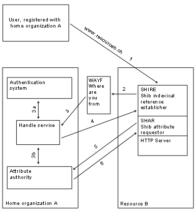
Figure 2‑20: Shibboleth architecture.
In Shibboleth, users access the web resources with a web
browser and are then HTTP-redirected to the respective Shibboleth services and
back. The web redirections use the HTTP command 302 “Temporary
Redirect”, which was originally invented for the temporary redirection to
a resource residing under a different URI. Technically, HTTP-redirections work
by putting the temporary URI in the location response header field of a HTTP
response. The user’s web browser must then perform a HTTP GET with the received
URI. The steps of accessing a Shibboleth protected resource are as follows (Steps
1) A user accesses the
Shibboleth protected resource B by contacting the URL of the web server, which
runs on resource B. The Shibboleth indexical reference establisher intercepts
the HTTP request, associating it with a handle suitable for attribute requests
by the Shibboleth attribute requestor. The handle is called Attribute Query
Handle (AQH).
2) The Shibboleth indexical
reference establisher redirects the user to the where are you from service. The
user manually selects his or her home organization in the list, presented by
the where are you from (WAYF) service. Passed together with the redirect to the
where are you from service are the handle acceptance URL and the user’s
initially desired target URL as parameters. The handle acceptance URL is the
URL, where the Shibboleth indexical reference establisher expects the attribute
query handle from the Handle Service (HS). Parameters are URL encoded with the
Uniform Resource Identifier (URI) generic syntax [BFIM98].
3) The where are you from
service redirects the user to the user’s home organization’s handle
service together with the Shibboleth indexical reference establisher
parameters, effectively acting as a proxy for the Shibboleth indexical
reference establisher. The handle service makes sure that the user is
authenticated.
4) The handle service sends
back an opaque handle associated with the user’s attribute
authority’s location to the Shibboleth indexical reference establisher's
"handle acceptance URL" by means of an HTML form posting conforming
to the SAML Browser/POST profile [SAMLBind]. The user's desired target URL is
passed as an additional parameter. Impersonation countermeasure information is
presented as well. The target URL is the URL to which the user's web browser is
going to be redirected after the handle has been accepted. The SAML response
form element contains a SAML protocol response, wrapped around an
authentication assertion, i.e. a base64-encoded XML instance document. The
Shibboleth indexical reference establisher, upon reception of the HTTPS request
at the handle acceptance URL, examines the in the form of a web browser/POST
incoming submission. The Shibboleth indexical reference establisher then sends
the extracted user data to another module loaded in the protected resource’s
web server, called Shibboleth attribute requestor. The Shibboleth attribute
requestor receives the user’s HTTP request URL, method, headers, an attribute
query handle, all authority binding information sent by the handle service and
the domain name of the organization that issued the handle.
5) The Shibboleth attribute
requestor sends an Attribute Query Message (AQM) to the attribute authority.
The query message uses the SAML syntax, embedded in a SOAP header.
6) The Shibboleth attribute
requestor receives an Attribute Response Message (ARM). Upon evaluation of the
attribute response message, the Shibboleth attribute requestor sends the
acquired attributes on to the resource manager (RM) that writes them into a
file and grants or not access to the protected resource, depending on the
resource’s Attribute Acceptance Policy (AAP). The attribute acceptance
policy is the rule set defining the attributes a resource requires for granting
access to a user.
Starting with the Shibboleth implementation version 1.3, it is
possible to interconnect multiple Shibboleth federations. A Shibboleth
federation is a community, which agrees upon certain common issues. In a
Shibboleth federation, it is necessary to specify and define typical things
such as the user information attributes. It is necessary to define which of the
attributes are mandatory or recommended and to specify the format of additional
attributes. It is necessary to specify the certificate authorities accepted
within and among the federations. Within a federation, it is necessary to organize
legal issues as a federation establishes common reliability among all its
members and the resources. For the interconnection of different Shibboleth
federations, it is necessary to deal with the same issues again, but on an
inter-federation level. From a technical point of view, the user information
attribute definition and the certificate authority acceptance policy are the
most important issues, whereas from the users’ point of view the data
protection issues invoked by the transfer of user information across federation
borders is the most important issue.
2.4.3 Point of Access to Providers of Information
Point of Access to Providers of Information (PAPI) [CL01] is
the authentication and authorization infrastructure mainly used by Spanish
libraries. The Spanish national research network provider RedIRIS [Rediris] has
developed PAPI. PAPI is a system for providing access control to restricted
web-based information resources across the Internet, independent from IP number
origin and open for mobile users. It intends to keep authentication as an issue
local to the user’s home organization, while leaving full control over
the resources to the information providers. The authentication mechanisms allow
each home organization to use its own authentication schema, maintaining user
privacy, and offering information providers the attributes required for access
control decisions. Moreover, access control mechanisms are transparent to the
user and compatible with the most commonly employed web browsers, i.e.,
Mozilla, Netscape, Internet Explorer, Lynx, and any operating system.
A PAPI-based authentication and authorization infrastructure
consists of the following components:
- Authentication server
The authentication server authenticates users from their
respective home organization. There is no preliminary authentication method
foreseen. Home organizations select their authentication method. The
authentication server has full knowledge about each user’s rights in the
PAPI environment. Users receive list of accessible resources.
- Point of Access to
resources (PoA)
Points of access to resources are the gatekeepers to the PAPI
protected resources. They act as a proxy and authenticate each web page
request.
Figure
2‑21 depicts PAPI’s main parts and shows how a user
accesses a PAPI-protected resource. Figure
2‑21 and the description originate from the
above-mentioned architecture document. We have slightly adapted both to our
discussion. All security assertions are placed into cookies. The single steps
described below show the security measures taken in this process. The resource
provider grants access based on visitor’s public attributes. PAPI guarantees
user privacy by a unique user code and only the respective home organization is
able to relate personal information to this code.
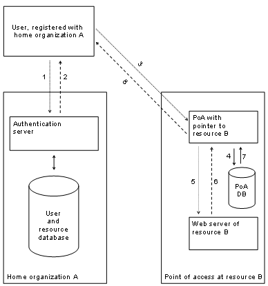
Figure 2‑21: PAPI architecture.
The steps of accessing a resource are as follows:
1) A user sends his or her
authentication data to the respective home organization’s authentication
server.
2) Upon a successful
authentication, the authentication server sends back a list of temporarily
signed URL of allowed points of access to resources for the respective user.
Each URL contains a user code, the authentication server, the expiration time
and the sign time.
3) The user accesses a point
of access to resources, which hosts the desired resource. He or she issues a
HTTP-request and sends two cookies to the point of access to resources. The
first cookie, the Hcookie contains the user code (a unique user identifier),
the authentication server, the expiration time and a random block. The second
cookie, the Lcookie contains the user code, the authentication server, and the
creation time.
4) The points of access to
resources stores the user information contained in the cookies in its database.
5) The points of access to
resources then perform a HTTP-request to the desired resource’s web
server.
6) The resource sends back the
web page to the points of access to resources.
7) New cookies are generated.
8) The web page together with
new H and L cookies are served to the user.
2.4.4 Remote Authentication Dial-In User Service
Remote Authentication Dial-In User Service (RADIUS) [Rc00],
nowadays also called remote network access security in an open systems
environment. It is a system for authenticating and authorizing users in access
networks, i.e. telephone networks, cell phone networks, modem pools and in the
Internet as well as for providing Point to Point Protocol (PPP) [Sw94] and
terminal server access. RADIUS furthermore offers accounting. IETF published the
RADIUS Request For Comments (RFC) document in 1997.
RADIUS bases on the client/server model. Clients pass user
information to the server and vice-versa. RADIUS servers manage users’
connection requests and authenticate them, return configuration information to
the client and execute accounting functions. RADIUS servers can also be the
linking unit to other RADIUS servers or other authentication infrastructures.
RADIUS traffic is encrypted with a shared secret, never sent over the network.
A user that accesses a network performs the steps shown in Figure 2‑22:
1)
A
user logs in into a network by providing a user name and a password.
2)
The
network access server being the RADIUS client passes the user information to
the RADIUS server. The server authenticates the user based on the information
stored in the user database and reads out client configuration data as well as
authorization information.
3)
The
server returns all the configuration parameters to the RADIUS client and the
user can access the desired service.
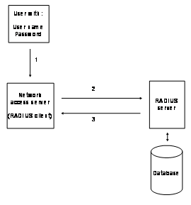
Figure 2‑22: RADIUS protected network access.
Over time, with the growth of the Internet and the introduction
of new access technologies, including wireless networks, Digital Subscriber
Line (DSL), Mobile IP and Ethernet, routers and network access servers (NAS)
have increased in complexity and density, putting new demands on
Authentication, Authorization and Accounting (AAA) protocols.
Diameter [CLGZ03] is a response to these new demands. Diameter
is a further development of RADIUS. The Diameter base protocol specifies the
components each Diameter implementation must include. These specifications
include the message format, the message transport mechanism, the error
messages, and the security services of the Diameter protocol. The applications
are on top of the base protocol.
One of most important enhancements in Diameter is authorization
based on user information attributes. Another important enhancement is the
simplified collaboration between different administrative domains.
Additionally to RADIUS, Diameter was also enhanced in the
following areas: error notification, extensibility through addition of new
commands and attribute/value pairs, basic services necessary for applications,
such as handling of user sessions.
A user that accesses a network performs the steps shown in Figure 2‑23:
1)
A
user logs in into a network by providing a user name and a password.
2)
The
network access server that is the Diameter client passes the user information
to the Diameter server in an authentication and authorization request. The
server authenticates the user based on the information stored in the database
and reads out client configuration data, as well as authorization information.
3)
The
server returns all the configuration parameters in an authentication and
authorization response to the Diameter client
4)
The
Diameter client sends an accounting message for the user and the respective
service to the server.
5)
The
server replies with a confirmation message and the accounting phase starts.
6)
When
the user terminates the session, the Diameter client sends an accounting
termination request to the server.
7)
The
server replies with a confirmation message and terminates the accounting
session.
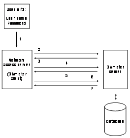
Figure 2‑23: Diameter protected network access.
2.4.6
The project with the name Liberty Alliance [Wt03 and LH02]
started in 2001 and aims to provide open standards for a trust network with an
emphasis on commercialization. Liberty Alliance is a response to
Microsoft’s Passport infrastructure but based on open standards and
implemented into the products of the Liberty Alliance compliant partners.
Liberty Alliance provides the necessary technical and legal specifications,
required for the interoperation of the infrastructure partners within and among
the Liberty Alliance federations. Liberty Alliance does not provide a framework
for charging and accounting yet but wants to provide this at a later stage.
Liberty Alliance resembles Shibboleth in many aspects and we thus compare the
features of both in the discussion of the Liberty Alliance. A main difference
is that in Shibboleth users go to resources directly and are then intercepted
by Shibboleth, redirected for authentication and access the resource, whereas
in Liberty Alliance, users go to a web portal belonging to an identity provider
and authenticate first. After authentication, users can federate their account,
which means that they authorize their identity provider to share their identity
to partners of this identity provider. This resembles customer loyalty programs
and emphasis the commercial orientation of the Liberty Alliance. It is well
imaginable that an airline maintains such a portal and operates the identity
provider. The airline then cooperates with hotels and car rentals. The own
customers cannot only federate their identity with these allies but they also
get softly pushed to use these services due to two reasons: They find the
allied enterprises on the portal of their identity provider, the airline.
Moreover, they can easily use their services by federating their accounts.
Liberty Alliance like Shibboleth exchanges user identity information through
pre-existing protocols and languages. Both use SOAP [BEKL00] for exchanging
application data and invoking programs on remote servers. Like Shibboleth,
Liberty Alliance also uses the XML subset SAML. Shibboleth and Liberty Alliance
use the authentication assertion, stating that a user U was authenticated at
time T by means M. Internet2, Shibboleth’s home organization, is a member
of the Liberty Alliance. Table
2‑6 compares Shibboleth with Liberty Alliance:
|
Feature |
Shibboleth |
|
|
Target
audience |
University
students, educational use |
Paying
customers, commercial use |
|
Active
privacy management |
Yes |
Yes |
|
Login
and Authentication |
Single
Sign-On with any authentication method chosen by the home organization |
Single
Sign-On with any authentication method chosen by the identity provider |
|
Single
Sign-Out |
No,
the authentication cookie’s lifetime determines the session end, no
real logout with the resources |
Yes,
the logout at the identity provider terminates the sessions with the service
providers |
|
Protocols
for authentication and authorization information exchange |
HTTP,
XML, SOAP, SAML |
HTTP,
XML, SOAP, SAML |
|
Fully
disclosed architecture specifications |
Yes |
Yes |
|
Software |
Shibboleth
issues open source Shibboleth software and provides it for download |
No,
Liberty Alliance does not implement provide any software. Liberty Alliance compliant
partners adapt their products |
|
Identity
providers |
Universities
|
Enterprises
|
|
Federations
(trust circles) |
Yes
|
Yes |
|
Number
of federations |
One
per country |
Many,
related to identity providers |
|
Federation
interoperability |
Yes,
with technical and legal agreements |
Yes,
with technical and legal agreements |
|
Benefit
for user |
Easy
resource access in the whole country, flexibility |
Easy
resource access with all partner resources of the identity provider |
Table 2‑6: Comparison of Shibboleth and
The Liberty Alliance’s goal lies in the design of an
architectural framework, which allows developing and delivering specifications,
to enable federated network identity management. The Liberty Alliance federated
network identity architecture comprises four modules. The slightly modified Figure 2‑24 originates from the Liberty Alliance architecture [LA03].
It depicts the four modules:
The
Liberty Identity services interface specifications
are a collection of specifications for interoperable services built on top of
modules 1, 2, and 3.
The
- Adopting and Extending Other Industry Standards
Liberty Alliance's architecture depends on
standards and specifications created within OASIS, W3C, and IETF. Module 2
integrates existing industry standards into the architecture.
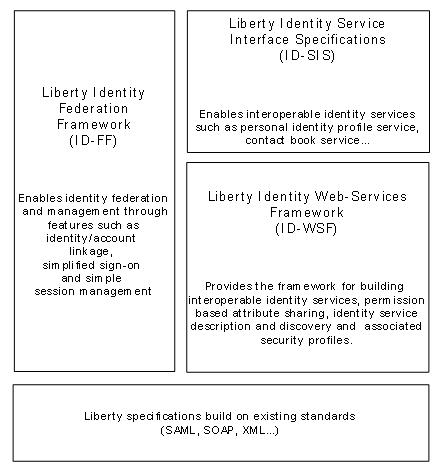
Figure 2‑24:
Figure
2‑25 depicts the UML sequence diagram of the Liberty
Alliance mechanisms. A user first authenticates with the identity provider,
called home organization in the Shibboleth environment. The user receives an
authentication cookie and accesses the web site of a service provider, called
resource in Shibboleth. The service provider accepts the authentication cookie
and asks for an account federation. With the account federation, the service
provider asks the user for the permission to use the user identity residing
with the identity provider. The user clears the federation request. He or she is
subsequently redirected to the identity provider, in a similar way as it
happens in Shibboleth with the Shibboleth indexical reference establisher. The
user sends an assertion request in a SAML compliant format to his or her
identity provider. The identity provider grants the assertion and the redirects
the user back to the service provider. The service provider now requests user
information attributes by the attribute provider, which is normally located by
the identify provider, in a SOAP/SAML compliant format. The user still has to
agree upon the attribute release towards the service provider, similar to the
process with the attribute authority found in Shibboleth. After receiving the
attributes, the service provider starts the service.
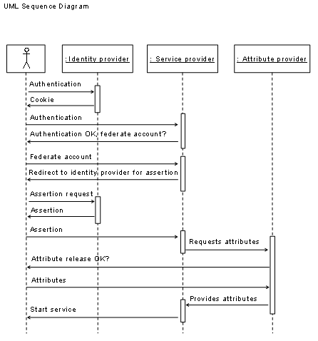
Figure 2‑25: UML sequence diagram of the
Microsoft .NET Passport [Passport] features one central
database where all sensitive system data is stored. Only one company
administrates this root server and has access to the stored data of all
affiliated organizations. Standards are not open and thus make the system
insecure compared to open source systems where the code is freely available and
anybody can verify it. Users cannot define their information release policy for
each resource they visit. Several severe security issues have been discovered
in the past.
The Microsoft Passport architecture comprises three entities:
- Passport Nexus is the
name of the root entity. This server stores the configuration information
and the mapping data for all participating servers in the Passport
environment.
- Passport servers are
the entities that issue passports to their respective users. Users have to
register with a Passport server that then stores their user data in a
database. Each Passport server provides a cookie to the user’s
browser.
- The Passport manager
entity runs at each resource site and reads the user cookies. Passport
managers can retrieve additional user information by the respective
Passport server.
2.4.8 Evaluation and Comparison of Authentication and Authorization Infrastructures
Shibboleth
Shibboleth allows distributed user management by the respective
home organizations and the connection of web-based resources, with a resource
access policy fully based on user information attributes. Participating home
organizations and resources agree on a common federation policy and use
commonly accepted public key certificates for the traffic encryption. Resources
do never see user credentials as users always authenticate with their home
organizations. Home organizations and users can decide which user information
attributes are released to resources and by this, actively influence the authorization
process. Resources authorize users by hand of the finally received user information
attributes. The user data management is transparent to users and user privacy
guaranteed. Organizations joining a Shibboleth implementation have to deploy
the origin site installation, which connects their user directory with the
infrastructure. Major disadvantages are the missing accounting and charging
mechanisms and the not yet fully implemented architecture, which at least now
does not provide users with full authority about their user information
attributes.
PAPI
The PAPI architecture allows the integration of distributed
user management and of distributed content providing resources. User privacy is
nevertheless an issue in the PAPI architecture. Authentication servers need to
know each resource a user is allowed to access. Particularly when having a
large number of resources this cannot scale, as the administrational work would
be immense to maintain these lists.
RADIUS
In RADIUS, authorization does not base on user information
attributes but on a database, which stores authorization data per user and
resource. The maintenance of this database is labor consuming for large user
communities with many users and resources. It gets more complicated, if users
and resources belong to several organizations and administrational domains. The
RADIUS architecture allows having a root server and delegate authority to
subordinate servers, such as the domain name service [AL94] does. Nevertheless,
this assumes that all involved parties agree with the service policy and with
the operators of the involved servers. This is not a realistic scenario, as
sensitive user information is visible for many user unrelated parties and it is
impossible to guarantee user privacy. Another negative aspect is that users
provide credentials to the resources, which operate the RADIUS client, and the
resources forward the credentials to the RADIUS servers. Malicious resources
can easily catch the user credentials. Another difficulty is the inter-realm
connection when it is impossible to connect the realms in tree like schemes,
but instead in a way similar to cross certification in public key cryptography.
Diameter
Diameter is an enhancement of RADIUS with interesting new
features. Particularly the user information attributes based authorization
makes Diameter a promising architecture, although it is not yet clear if users
can selectively release user information attributes per resource. User
information attributes bring their benefits to users only, if users can
selectively control who receives them. Diameter is a very recent development
and implementations are rare. Up to now, only few applications exist in the
telecommunication industry. Diameter has overcome the drawbacks existing in
RADIUS, to this time at least theoretically. As the telecom industry pushes
Diameter, implementations in this area will show up in future. We assume that
Diameter will reach a higher popularity than RADIUS did.
Liberty Alliance is still in the architectural defining phase
and not all the necessary documents for the implementation are ready. Liberty
Alliance announced to release the specification documents in mid 2004 but not
all the documents were ready. Each Liberty Alliance partner has to implementation
the specifications in the own equipment. A finished open source implementation
does not yet exist. The principles of the architecture are interesting and make
it a serious option for future authentication and authorization networks with accounting
support.
Passport
Microsoft’s architecture is an interesting architecture
but unfortunately gives too much power to one single enterprise. It is
impossible to guarantee user privacy and data protection. This prevents
Passport to be a serious candidate for our architectures, although we could
implement interfaces towards Passport if necessary in a later phase.
Comparison and Recommendations
The features of each of the six evaluated secure data transport
technologies are condensed and compared in Table
2‑7. Features provided are marked as X, features provided
under certain conditions as (X):
|
|
Shibboleth |
PAPI |
RADIUS |
Diameter |
|
Passport |
|
User
information attribute-based authorization |
X |
|
|
X |
X |
|
|
Easy
inclusion of organizations possessing a user database |
X |
X |
X |
X |
X |
X |
|
Multi
domain interoperability natively supported. |
X |
X |
|
X |
X |
|
|
Authentication
remains with users’ home organizations. |
X |
X |
|
|
X |
|
|
Open
source based |
X |
X |
X |
X |
X |
|
|
User
privacy guaranteed |
X |
X |
|
X |
X |
|
|
Allows
integration of a public key infrastructure. |
X |
X |
|
X |
X |
|
|
Accounting
supported |
|
|
X |
X |
X |
X |
|
Federated
user management |
X |
X |
|
X |
X |
|
|
Deployed |
X |
X |
X |
(X) |
|
X |
|
Supported
by telecom industry |
|
|
X |
X |
|
|
|
Supported
by industry |
X |
|
X |
X |
X |
X |
|
Designed
for roaming users |
|
|
|
X |
X |
|
|
Easy
inter-realm connections |
X |
X |
|
X |
X |
|
|
Home
organization specifies accessible resources per user |
|
X |
X |
|
|
X |
|
Resources
must be adapted |
X |
X |
X |
X |
X |
X |
|
Not
yet fully implemented |
X |
|
|
X |
X |
|
|
User
controls information attribute release per resource |
X |
|
|
? |
X |
|
|
Known
for security problems |
|
|
|
|
|
X |
|
Centralized
architecture |
|
|
X |
|
|
X |
Table 2‑7: Comparison of authentication and
authorization technologies.
Evaluation recommendation: Our recommendation result
is the similar to the inter-university working group in
The best authentication and authorization infrastructure in a
multifunctional e-learning architecture is the lightweight directory access
protocol. It offers user authentication, user authorization, and laboratory
device authorization; functionalities required in architectures with a central
resource management system in combination with a reservation system and geographically
distributed content servers. An advantage of the lightweight directory access
protocol is the possibility to add users automatically to the database by a
root user management system. We recommend using the lightweight directory
access protocol for the multifunctional e-learning architecture.
Secure Sockets Layer is a technology for the encryption of
application traffic in a simpler manner than with IP Security. We recommend
using secure sockets layer technology for HTTPS and encrypting web pages
between clients and servers, especially because users profit from encrypted
traffic and do not have to configure or install extra software. We recommend
using secure sockets layer also for Stunnel. Stunnel links are set up fast and
protect data sent from one IP number port to another.
IP Security is a technology with advantages if used for transferring
encrypted data from server to server. We recommend using IP Security for the
encryption of all server traffic in the e-learning architecture. If the
implementation of IP Sec is not feasible, we recommend using Stunnel.
Secure Shell is an application that provides the same
functionalities as Telnet shells do but with the enhancement of encrypting the
traffic. We recommend using secure shells for the access to laboratory devices.
For the extended multifunctional e-learning architecture, we
recommend using Shibboleth as the root authentication and authorization
infrastructure. We also recommend shifting authentication from the lightweight
directory access protocol to Shibboleth.
Although Kerberos is a state-of-the-art authentication
infrastructure, it does not contain authorization functionality required for
user access and laboratory device reservations. The Kerberos inter realm
connectivity with the key management, also with integrated public key
infrastructures, is not as simple to integrate in an e-learning architecture
such as possible with the lightweight directory access protocol or with
Shibboleth.
Two technologies were not yet ready in the time this work was
performed. Diameter and Liberty Alliance are potential candidates for the
future, which could replace Shibboleth. Liberty Alliance does not produce own
software and limits its activities to the specification of technical and legal
frameworks. Liberty Alliance thus will never release a Liberty Alliance
conforming infrastructure as code ready for the implementation. Nevertheless,
it is hypothetically possible that Shibboleth developers make Shibboleth
compatible to Liberty Alliance specifications. It would also be necessary for
the Shibboleth federations to adapt their federation specifications to the
Liberty Alliance specifications.
It is important to keep an eye on the environment in which an
e-learning architecture has to run. The best e-learning architecture is useless
if not supported by home organizations and resource providers. A consequence is
that there might exist better technological solutions or self-developments, but
it would be necessary to operate them in a solo attempt.
It is vague to make a prognosis as all infrastructures are
further developed and new evaluations will have be necessary all the time we
have to address new questions regarding required architectural extensions or
changes.
2.6 Computer Networks Laboratories
For a better understanding of the e-learning version and the
designed architecture, we present the technical settings of an exemplar traditional
computer networks laboratory as found at our university. Subsequently we
present other e-learning laboratories.
2.6.1 Traditional Laboratory Architecture
Before we can address technical and didactical questions of an
e-learning laboratory, we have to understand traditional computer networks
laboratories. We investigated the in-house laboratory located at our
institution. Computer networks laboratories with similar set ups exist in most
organizations involved in the education of computer science students. Students
meet on-site at the laboratory if they have to perform hands-on trainings. In
our case, the laboratory consists of a laboratory server and six laboratory
clients as shown in Figure
2‑26. The laboratory server bootstraps the hosts and else
remains disconnected during the hands-on trainings. In such a setting, two
groups can work independently from each other.
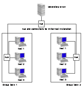
Figure 2‑26: Layout of the traditional laboratory.
The laboratory server hosts preconfigured hard disc images with
the necessary software for each host and exercise module. This setting allows a
fast and clean re-initialization of the hosts after each training. For the
laboratory client installation, we use a tool called Fully Automatic
Installation (FAI) [GLR99]. FAI is a non-interactive system for installing
Debian GNU/Linux on networked machines. FAI was adapted for the SUN Sparc architecture
at our institute.
Each student group can work on three hosts and inter connect
hosts with repeaters and switches. There is also a set of two commercial
routers. We use the routers in modules about static and Routing Information
Protocol (RIP)-based routing and about virtual private networks.
Appendix B lists the available modules of the traditional
laboratory.
Our distributed e-learning architectures address access questions related to distributed content providing comprising laboratories with real network equipment but operated at geographically distributed locations. Our prototypically implemented e-learning computer networks laboratory course consists of theory chapters, exercises, hands-on trainings on real network devices and simulation tasks in a modular course framework. This is a new approach for forming an e-learning grid. The below discussed computer networks laboratories all offer some but not all of the functionalities our discussed architecture and prototypical implementations provide. Other computer networks laboratories do not integrate work on real devices but on emulations or simulations only. Not all laboratories are full courses with theory and exercises integrated. Others open the laboratory devices to the entire classes during a certain time interval.
One User Name and Password Courses
We call courses one user name and password courses, when a user name and password is necessary for student access to the e-learning laboratories but all students use the same user credentials. Such an approach is feasible with a centralized and a distributed architecture. The main limitation is that there must be more available laboratory equipment and laboratory facilities than students who want to access them or students have to respect laboratory access schedules voluntarily.
A disadvantage of this approach is that tutors never know who exactly accesses the laboratory hardware and performs which exercise. It is not possible to make personalized accounting and charging. Subscribed students can perform the exercises but an automated and personalized evaluation is impossible. In this approach, it is not possible to exclude the possibility of multiple logins of students to laboratories with the negative impact of interfering with running exercises of other students. There is also the possibility that students distribute their credentials and non-paying users work in the laboratories.
The
“Verband der Elektrotechnik
Elektronik Informationstechnik e.V.” (VDE), operates such a computer
networks laboratory, which gives access for whole classes with one identical
user name and password only. The technical
Nevertheless, the course fulfilled the requirements of the commercial operators and students. There is no scientific publication referencing this course with the exception of one from us and in 2005, the course page was no longer available.
Evaluation
This teaching approach is better suited for blended learning, where students regularly meet in traditional lectures than for e-learning. We think that complete e-learning courses should comprise interactive theory, exercises, and hands-on trainings and allow an automatic and individual evaluation, accounting and charging of the students.
Personalized Courses with Centralized Architecture
We call courses personalized courses with centralized architecture when each user accesses the course with own credentials. In this approach, it is possible to perform accounting and charging for each individual user. The course system can automatically evaluate student tasks and tutors investigate each step of each user if desired. Students can book laboratories and do not interfere with other students during the hands-on trainings. The centralized course architecture simplifies the protection from Internet threads as no course management data between geographically distributed course servers crosses the Internet.
Former Mentor Technologies from the
During the live demonstration in 2002, we saw that Mentor Technologies operates a state-of-the-art course system, which comprises a resource management system and a laboratory reservation system. The courses offered theory, exercises, and hands-on trainings on real network equipment. The course content was especially adapted to the Internet and enriched with interactive animations. Students could always contact tutors for live support.
Students accessed their course via a proprietary web interface s in the form of a Java applet. This web interface embedded communication features to the tutors, comprising audio and text chat.
Evaluation
The e-learning approach Mentor Technologies used is very interesting. We miss the possibility to provide the content from geographically distributed locations for forming an e-learning grid. The main disadvantage we see in this approach is the non-disclosure of the architectural and technical background. We can only learn from what we have seen in the live demonstration and consider it as input in the conceptual discussion of our own approaches.
Personalized Laboratories with Distributed Architecture
We call laboratories personalized laboratories with distributed architecture when several laboratories at geographically distributed locations are organized in one entity. There exist laboratories with resource operators distributed all over the world. It is possible to use such laboratories in students’ education.
The main users, in particular of the large entities comprising several hundred laboratories are designed for researchers and engineers. The main advantage is the possibility to create overlay networks with real equipment and traffic routes through the Internet for performing measurements under real life conditions.
In such entities, it is necessary to control access to the distributed equipment. A reservation system must allocate resources to the users. It is also essential to reset the configuration of the laboratories for each new user.
PlanetLab [PACR02] is one of those entities, forming a global grid for real life measurements. Universities can join PlanetLab by providing a minimal number and quality of computers and Internet connectivity as well as a reset device for the computers. PlanetLab’s resource management system is then responsible for the resource allocation to the users. Several universities use PlanetLab additionally for hand-on trainings for their students. The book resources and let students perform predefined exercises.
Evaluation
The approach with personalized laboratories in a distributed architecture is interesting, in particular in the case of PlanetLab. Features such as resource allocation, root access to nodes and the reset possibility for the devices must be a part of a state-of-the-art e-learning computer networks laboratory. We do not recommend the use PlanetLab itself for the laboratories as administrative control for these devices is with PlanetLab. PlanetLab exclusively provides nodes and no other network equipment. This would limit a common computer networks laboratory, where for example also routers, switches, and wLAN base stations make part of the exercises.
Personalized Laboratories with Emulated Nodes
We call laboratories personalized laboratories with emulated
nodes when it is possible to grant access to single users and all the nodes are
emulated. An advantage of emulated laboratories is that several nodes can run
on one physical machine. In such cases, it is essential that the nodes do not
influence the other nodes, for example in the consumption of CPU and memory
capacity. In such laboratories, nodes must often used to emulate routers and
other network equipment. The use of emulations on powerful computers provides
immediately a high number of configurable devices for measurement or educational
purposes. Resource owners may save money with the administrators and maintenance
of emulations in a centralized system.
There exist several federated, huge network laboratories built on the EmuLab [WLSR02] technology. Within the project "EmuLab Classic”, they offer access to several hundred computers to do network emulation and experimentation. Universities are able to request the resources for experiments and get full access to a certain number of nodes. Users access the laboratory devices through secure shell clients or web interfaces. It is possible to use the computer nodes as edge nodes and running arbitrary programs, simulated routers, traffic-shaping nodes, or traffic generators. While an experiment is running, the acting users can exclusively use the assigned machines, including root access.
Evaluation
A difference to our approach is that EmuLab emulates hardware and does not provide access to real devices. Emulations do rarely contain all the functionalities of sophisticated devices such as computers and nodes represent. An update of emulated devices, for example to a new firmware version requires adaptation of the software whereas in laboratories with real devices it is possible to update the firmware in a short time or to exchange the device. Once emulations are implemented, much more users can work on them compared to expensive real devices.
3
Resource
Management Portal
3.1 Components and Interactions
The term authentication and authorization infrastructure is
used for the mechanisms and protocols used to link all home organizations,
resources and users together. Authentication and authorization infrastructures are
middleware and should remain mostly invisible to users. There are few
opportunities where users get into contact with web interfaces, for example to
specify their information release policy. The authentication and authorization
infrastructure must obey to the local data protection laws.
An authentication and authorization infrastructure architecture
environment with non-AAI-enabled and AAI-enabled resources most likely consists
of the elements shown in Figure
3‑1. Additionally to the typical elements, the Figure also
depicts non-AAI-enabled but resource management portal-enabled resources behind
the resource management portal.
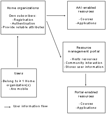
Figure 3‑1: Typical AAI environment with the resource
management portal.
- Home Organizations
(HO) are universities or other entities, where potential resource users
such as students and staff members are registered. Home organizations perform
user registration and comply with the authentication and authorization
infrastructure policy, defining the rule set with the common standards for
users and resources. Such a rule can for example define the nomenclature
of the unique user identity, which home organizations have to generate for
each user. In the case of Shibboleth, this attribute is in the form of encrypted
characters @HomeOrganization.ch (i.e. fg98wessed@unibe.ch). Home
organizations maintain the databases with the data of the registered
persons. The database must have an interface to the authentication and
authorization infrastructure. Home organizations only authenticate their
own members.
- Users possess at least
one account at their respective home organization. Home organizations
exclusively authenticate their users. A user may be a member of more than
one home organization and have more than one role in a certain home
organization, for example as student and tutor in different units of the
home organization. Users obey the home organizations policy, which itself
is conforming to the authentication and authorization infrastructure
policy. Through the attribute release policy, users determine which
personal data the home organization can to release to resources.
- Resources are
web-based resources or services offered by providers to users of the
authentication and authorization infrastructure. Resources belong either
to the group of AAI-enabled or non-AAI-enabled ones.
- AAI-enabled resources
connect directly to the authentication and authorization infrastructure. They
have specific interfaces to the authentication and authorization
infrastructure. Based on users’ attribute release policy and
resources’ Attribute Acceptance Policy (AAP), users are able to
access resources. This is a case of user authorization executed by the
users and by the resource owners. Only users providing the required
attributes can access the resource. Enabling resources for authentication
and authorization infrastructures is expensive and time consuming. Since
each authentication and authorization infrastructure is unique, it is
necessary to re-implement resource interfaces for each kind of
authentication and authorization infrastructure and resource.
- It is impossible to
connect non-AAI-enabled resources to authentication and authorization
infrastructure directly as they lack the specific interfaces to the
authentication and authorization infrastructure. Therefore, authentication
and authorization infrastructure users cannot access those resources and
take profit from AAI-related benefits such as Single Sign-On (SSO) or
attribute release and acceptance policies.
- The portal is a broker
between the authentication and authorization infrastructure and the hosted
resources. The hosted resources must be adapted to the portal but have not
to be re-adapted to each update or change of the authentication and
authorization infrastructure.
Authentication and authorization infrastructures provide
advantages for all involved parties. The integration of the resource management
portal as a broker makes it possible to provide those advantages also to
non-AAI-enabled resources and to provide enhanced user and resource management
features:
- The advantages of
connecting resources to authentication and authorization infrastructures
lie in the decreased administrational overhead and the reliable user
information in the form of user information attributes provided by the
user’s home organization. Resources define their access policy based
upon required user information attributes instead of user identities.
Further internal resource user management, such as internal resource access
levels or user roles remain a resource internal issue unaffected by the
authentication and authorization infrastructure.
- The advantage for home
organizations lies in the immediate increase of accessible resources for
their members. Authentication and authorization infrastructure users belong
to their respective home organizations and have to agree with the local
subscription policy. Home organizations define their information release
policy to protect their members’ privacy on the one hand and on the
other hand to enable members to access resources. Resource providers
reduce administrational overhead, as they do not have to manually verify
and subscribe foreign persons to their own AAI-connected resources.
- The advantage for
users lies in a simplified resource access procedure. No on-site or mail
registration procedure is needed. It is a precondition in authentication
and authorization infrastructures that user information released by home
organizations is reliable and accepted by the resource providers. The
privacy sphere is guaranteed in two ways: First, users still authenticate
with their own home organizations and never with resources. Secondly,
users determine which user information attributes about themselves are
released to the resource they want to access.
Figure
3‑2 shows a resource owner’s site. The resource
management portal has pluggable interfaces to each type of connected authentication
and authorization infrastructure and resource. The authentication and
authorization infrastructure interface is responsible for the resource
owner’s site connection to the authentication and authorization infrastructure.
If users, belonging to such an authentication and authorization
infrastructure-connected home organization, access resources hosted by the
resource management portal, the resource management portal receives user
information attributes from the authentication and authorization infrastructure
interface and stores them in its database. Users who successfully subscribe to
a resource management portal hosted resource agree with the transfer of
selected user attributes to the resource on demand of the resource. The
resource may store user data in its own database or relay on the resource
management portal’s database. It is possible that the resource sends back
user information to the resource management portal. Beside the access
management, the resource management portal provides enhanced user management.
The portal allows resources to ask users directly for additional information
and enables users to manage self-provisioned user information. The portal
further contains basic and enhanced e-community interaction tools (community
interaction tools designed for the Internet), which can be added in a modular
way.
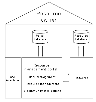
Figure 3‑2: The resource management portal at a
resource provider’s site.
Figure
3‑3 shows the interaction diagram for users connecting to
the resource management portal. We discuss the two cases separately. Both end
with the common HTTP-redirection to the resource:
- In the first case, a
user with a local account on the portal connects to the portal. He or she
must provide the credentials and upon a successful authentication accesses
the portal.
- In the second case, a
user with an account from a home organization, connected to the same
authentication and authorization infrastructure as the resource management
portal, connects to the portal. It depends on the authentication and
authorization infrastructure if users are HTTP-redirected to their home
organization for authentication or if the portal integrates the
authentication mechanisms locally and if user information attributes are
supported. In the case of Kerberos the portal would be Kerberos-enabled
and users be authenticated by the key distribution center. In the case of
RADIUS, the portal would act as a RADIUS client and contact the RADIUS
server to authenticate and authorize the user. In the case of PAPI, the
user would get a list of resources he or she is authorized to access upon
a prior authentication with the home organization. In the case of Shibboleth
and most probably also of Diameter, the user is immediately
HTTP-redirected to the authentication system of the respective home
organization. Upon a successful authentication, the user is
HTTP-redirected back to the portal and the home organization may release
user information attributes by means of the authentication and
authorization infrastructure to the portal.
After choosing a subscribed resource, the user is
HTTP-redirected to the resource. The interface, which redirects the user to the
resource, may also send user information stored in the resource management
portal’s database to the resource.
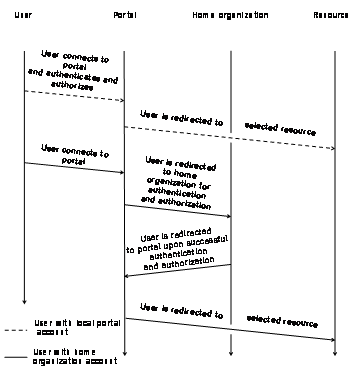
Figure 3‑3: Interaction diagram for connecting users.
Figure
3‑4 depicts the interactions happening in authentication
and authorization infrastructures such as Shibboleth, when resources request
user information attributes from users. User A, belonging to a home
organization with the name institution Y tries to access resource X. A’s
home organization as well as the resource X belong to the same authentication
and authorization infrastructure. Upon the first contact with the resource, the
resource redirects user A for authentication to the home organization institution
Y. Upon a successful authentication, the resource X requests user information
attributes about A from institution Y. Institution Y stores those user
information attributes for all their users. Institution Y now checks A’s
user information attributes release policy for the resource X and then checks
if these attributes lie within the home organization’s attributes release
policy. The home organization then releases those attributes matching both release
policies to the resource X. Resource X receives those attributes and compares
them with the own attribute acceptance policy, describing which information attributes
are required so that user A can access the resource. If A’s home
organization provides the requested attributes, he or she can access the resource
X.
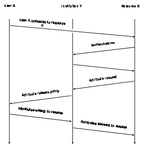
Figure 3‑4: Attributes release and request.
3.2 Architectural Specifications
This Chapter describes the resource management portal’s
design and architecture. After a short listing of key features, the portal provides
for user, resource, and community interaction, we present the plug-in concept
and discuss the overall functionality of the resource management portal. We
then present the proposed user roles on the portal and the possible user
interactions with the resource management portal.
Resource Management Portal
Architecture’s Key Features
The portal provides many features for resource and user
management. The list below represents a summary of the key features:
- Hosting of one or
multiple resources.
- Resource-related
management functions.
- Resources can be
visible or invisible on the resource list.
- Resources can be open
or closed for subscription.
- Resources can be set
open for all or subscribers put on a waiting list where tutors can
manually grant or deny access.
- Resource can be
suspended.
- Resources can be
deleted from resource management portal.
- Users can be blocked
out from resources.
- Users can be notified
about status changes by Short Message Service (SMS) or Email.
- Tutors can notify
their users by Short Message Service or Email.
- Additional community interaction features can
be added on a modular base, such as chat.
- Attribute request
policy can be set individually for each resource.
- Attribute release
policy can be set individually by each user and for each resource.
- Missing attributes
according to the resource’s attribute request policy can be requested
from the user.
- User provided
information appears as `user provided` in the database.
The authentication and authorization infrastructures as well as
the resources must be pluggable into pre-defined interfaces. With such an
interface concept, it is possible to implement rapidly new interfaces. The
advantage of this plug-in concept lies in the possibility to reuse the
interfaces. Once an interface (called resource adaptor in the context of the
resource management portal) is available, other similar resources can reuse a
resource adaptor or adapt it accordingly to their own needs. Figure 3‑5 depicts the interfaces as plugs and connectors, which
have to fit to each other. Technically, application programming interfaces
represent the interface on the resource management portal On the left side
three authentication and authorization infrastructures are depicted, each of
them with an own interface. On the right side, we see four example resources.
In this case, each of the resources uses a different resource adaptor.
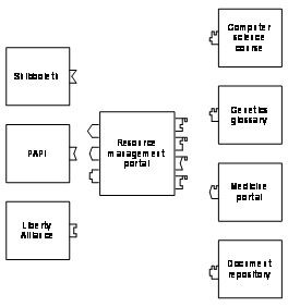
Figure 3‑5: Resource management portal with interfaces
to AAI and resources.
The resource management portal itself must become an
authentication and authorization infrastructure-enabled resource towards each
of the plugged authentication and authorization infrastructures, and a user,
resource, and community interaction portal towards resource owners and users. Figure 3‑6 depicts this broker function with the plug-ins towards
a resource and an authentication and authorization infrastructure as well as
the two different roles the resource management portal plays.
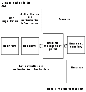
Figure 3‑6: The resource management portal’s
environment.
This Chapter aims to put the resource management portal and its
various modules into context with its interacting neighboring systems. It
visualizes and describes the user information attribute flow from home
organizations towards the resource management portal and its hosted resources,
describes the interfaces towards authentication and authorization
infrastructures and the chosen adaptor concept. We present the concept for the
interfaces to resources, called resource adaptors and address the concept of
the interfaces for enhanced community interaction features, pluggable into the
portal. We also discuss accounting aspects of the resource management portal
and authorization issues sometimes raised with certain resource types.
Broker Functionality
Figure
3‑7 shows the functional parts of the resource management
portal. On the left side we see the interfaces for the authentication and authorization
infrastructures, which could be more than one at a time and from directly
connecting users. The connecting unit links the interfaces to three user areas.
Connecting users can access the resource management portal’s areas
depending on their defined user role described below. On the right side, we see
the interfaces to a set of hosted resources. There is no minimum or maximum
number for hosted resources. Resource and portal owners must design each of the
interfaces, either to an authentication or authorization infrastructure or to a
resource individually but can reuse the adaptors again whenever the same type
of authentication and authorization infrastructure or resource is reconnected.
The resource management portal’s database stores collected data such as
user information attributes or user provided information.
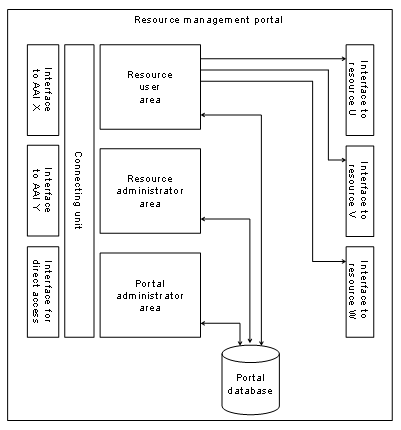
Figure 3‑7: The functional parts of the resource management portal.
User Information Attributes’ Flow
Figure
3‑8 shows the user information attributes’ flow
from a home organization through the authentication and authorization
infrastructure to the resource provider for a resource hosted by the resource
management portal. Reliable user-specific information attributes originate from
the user’s home organization or as non-reliable user information
attributes by the user on the resource management portal itself. The resource
management portal stores all gathered user data (the user information
attributes) in its own database and, upon a successful user subscription to a
resource, may store the respective user data set into the resource’s database.
The resource may also query the resource management portal’s database
directly in the case the resource does not maintain an own database. The
resource’s database may be used for read and write access by the resource
and by the resource management portal, if required. If the resource management
portal for example adds a user to a resource’s database, it can check if
the user already exists and then add the user to the requested part of the
resource instead of generating a completely new user profile on the resource.
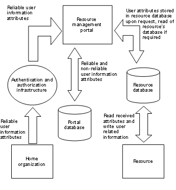
Figure 3‑8: Resource management portal architecture’s
user information attributes flow.
Attributes flow from the home organizations through the
authentication or authorization infrastructure to the resources, the reverse is
not foreseen, although one could imagine it. A reverse attribute flow from
resources to home organizations is for example necessary for a financial
accounting or for a reporting of students’ work results. It is also
possible to retrieve attributes from the resource management portal by the home
organizations through special users who poll the resource management portal for
resources’ data they may access.
Figure
3‑9 depicts the resource management portal’s configuration
flow chart in the form of an UML activity diagram. Figure 3‑10 shows the same but as an UML sequence diagram. An
unknown person enters on the top left side and first authenticates with his or
her home organization. The now authenticated person, called user Bob hereafter
on, gets to the web interface for resource selection on the resource management
portal. The web interface lists resources, which are unsubscribed, subscribed,
or pending for subscription. In a next step, the resource management portal
checks for all needed data (authorization) depending on the resource’s
attribute acceptance policy. If there are missing attributes (in other words,
attributes which are not delivered by the home organization), the user is directed
to the resource management portal’s web interface for collecting user
data.
Missing user attributes collected on the resource management
portal are clearly marked as non-reliable attributes. If the attributes satisfy
the resource’s attribute request policy, the resource management portal
checks if the user is a new or existing subscriber of the resource. In the case
of a new subscriber, the resource management portal verifies if there is a
waiting list for the subscribed resource. The portal redirects already
subscribed resource users with granted access and new resource users accessing
resources without waiting lists the resource. The portal prepares user data for
new subscribers of resources without waiting list and stores it in the respective
database. For resources with waiting list, subscribers get to the waiting list,
where an administrator has to deblock them. Upon deblocking user data, the
resource management portal database is updated and the status of the deblocked
resource changed on the resource list of the respective subscriber. Those
subscribers login again later and follow the already described way for
previously subscribed users. The administrator logs-in and gets to the administrator
interface where he or she accepts or rejects pending subscription requests of
the waiting list.
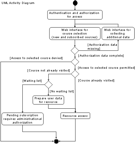
Figure 3‑9: UML activity diagram for resource
management portal configuration flows.
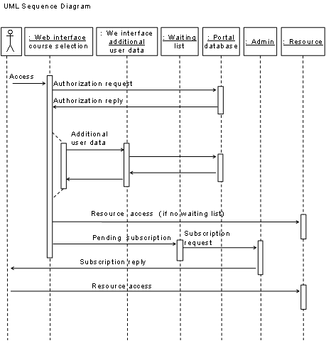
Figure 3‑10: UML sequence diagram for the resource management configuration flows.
Interfaces to AAI (AAI Adaptors)
The resource management portal’s interface to the
authentication and authorization infrastructure receives user information
attributes from the authentication and authorization infrastructure. Each type
of authentication and authorization infrastructure provides attributes in a
different way. Figure
3‑11 shows the principle of the attribute flow towards the
resource management portal. In the case of Shibboleth, the web server receives
SAML encoded user information attributes from the user’s home
organization and writes them into a file, which is accessible by resources. In
this case, the authentication and authorization infrastructure adaptor
reads-out the file and imports the data into the portal’s database. In
PAPI’s case, PAPI encrypts and sends user information attributes via cookies
to the web server, where the authentication and authorization infrastructure adaptor
reads-out user information data. The resource management portal’s pages
are .htaccess access protected. The term “.htaccess” stands for a
file which indicates who is able or not to access a file or folder in the web
server’s directory. If the resource receives the requested user
information attributes, the respective user can access the portal’s
pages.
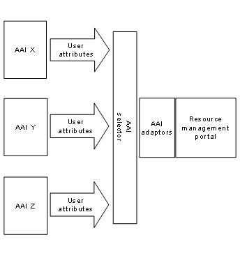
Figure 3‑11: Interfaces to AAI.
In Figure 3‑11 the resource management portal is connected to two
different authentication and authorization infrastructures. The authentication
and authorization infrastructure selector gives the users the possibility to
choose their proper authentication and authorization infrastructure. The
situation of having more than one specific authentication and authorization
infrastructure connected to the resource management portal opens resource
owners the possibility to distribute their content to more than one user community,
without having to invest a lot of money for resource adaptations.
We call interfaces to resources resource adaptors in the
context of the resource management portal. There is no general way to connect
external resources to the resource management portal because each resource has
its own authentication and authorization system and security properties, which
have to be adapted to portal.
One goal of the resource management portal is to integrate
easily new resources. Therefore, an implementation of the resource management
portal must offer an application-programming interface with at least the
possibilities to:
- Read-out user data
from the resource management portal database.
- Write user data into
the resource management portal database.
- Read resource data
from the resource management portal database.
- Write resource data
into the resource management portal database.
- Display a help text to
a specific resource adaptor.
- Create a resource
specific database on the resource management portal, accessible by the
resource.
In general, the resource management portal HTTP-redirects users
to the resource and provides the requested user information to the resource as
shown in Figure
3‑12. Figure
3‑12 shows different resources, which require different
types of resource adapters. Only if resources use identical authentication and
authorization systems, resource adapters it is possible to reuse them without
changes. A recommended user redirection to a resource sends opaque user
information to the resource, decipherable only by the resource.

Figure 3‑12: Interface to resource.
As there are many different resource adaptors imaginable, we
present a selection of possible scenarios with the corresponding resource
adaptors. The selection is not complete and each presented scenario is
extensible in many different aspects. Suppose for each case that user Bob
accesses the resource management portal and chooses to access the resource
Vanilla. Bob is a subscribed and accepted user of this resource. Bob’s
home organization has provided all the necessary user information attributes to
the resource management portal necessary to access the resource Vanilla.
Scenario 1: Simple user redirection.
Resource vanilla does not need any information about Bob, and
therefore, Bob is only HTTP-redirected to Vanilla as depicted in Figure 3‑13. The UML activity and sequence diagrams show, how a
user selects a subscribed resource and is redirected to the resource. Figure 3‑9 depicts the details in case the user has not yet subscribed
to the resource. This is the simplest type of a resource adaptor and only
listed for the sake of completeness as such a resource does not really need an
authentication and authorization infrastructure or the resource management
portal.
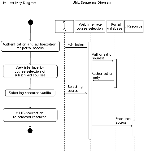
Figure 3‑13: UML activity and sequence diagrams for access to unprotected resource.
Scenario 2: User redirection with
cookie containing user name and password.
Resource X wants to restrict access to authentication and
authorization infrastructure users but keep a user name and password-based
access procedure. Figure
3‑14 depicts the UML activity diagram and Figure 3‑15 the UML sequence diagram for this scenario. User A possesses
an encrypted and time stamped cookie with a limited validation length containing
A’s user identity (uid) and password. The resource management portal generates
the password and A does not know it to prevent a direct login to the resource.
A direct login to the resource would take off admission control and accounting
functions from the resource management portal. The portal has to store user
name and password into the resource’s database before it redirects A to
resource X. X checks whether the cookie is valid and the user exists in its
database. This scenario is interesting for existing resources, which cannot be
re-programmed and/or must remain with user name and password access control
mechanism.
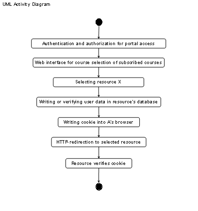
Figure 3‑14: UML activity diagram for access to cookie
protected resource.
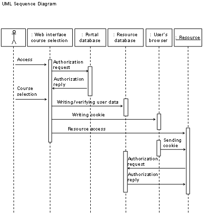
Figure 3‑15: UML sequence diagram for access to cookie
protected resource.
Scenario 3: User redirection with the
generation and display of user name and password to the user.
Figure
3‑16 depicts the UML activity diagram and Figure 3‑17 the UML sequence diagram of scenario 3. The resource
management portal generates a user for the resource X and first stores the user
name and password in the resource’s database. Secondly, it displays them
to A in the form of an image, additionally to the recommended SSL or HTTPS
transmission for security reasons (it is easier to scan and process traffic for
passwords if it is in clear text). A is now HTTP-redirected to X and has to
provide user name and password. We recommend using this scenario for one time
logins only as A could login directly to the resource if user name and password
remain valid after the first session.
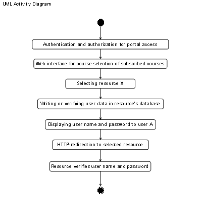
Figure 3‑16: UML activity diagram for access to user
name and password protected resource.
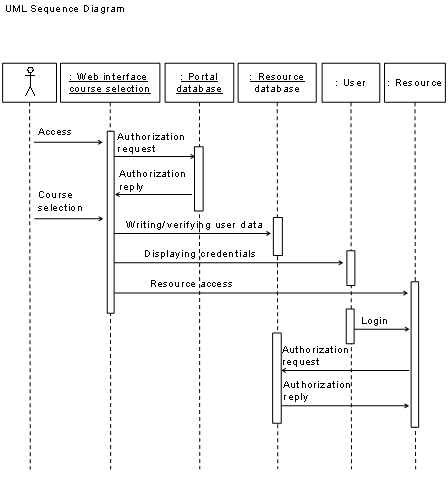
Figure 3‑17: UML sequence diagram for access to user name and password protected resource.
Scenario 4: User redirection with URL
Get/Post or a cookie plus additional attributes together with a shared secret.
Figure
3‑18 depicts the UML activity diagram and Figure 3‑19 the UML sequence diagram for scenario 4. The resource
management portal prepares the resource access credentials for user A. The
portal stores this information in a cookie and writes it into A’s browser
or adds the credentials to the URL in the HTTP-redirection step by the Get/Post
method. The information is encrypted with a shared secret known by the resource
management portal and resource X. When A accesses X, X verifies the shared secret
and if it is A’s first access stores A’s user information in its
database. In this way, user A can access the resource through the portal with
an HTTP-redirection or if he or she knows the resource’s URL directly.
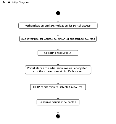
Figure 3‑18: UML activity diagram for the access to
resource by means of a shared secret.
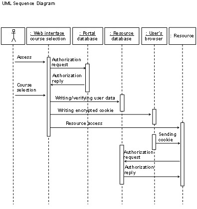
Figure 3‑19: UML sequence diagram for the access to
resource by means of a shared secret.
Resource management portal administrators see a list of
built-in resource adaptors in the resource configuration screen. It is possible
to choose each of the built-in resource adaptors for the integration of new
resources or exchange against other resource adaptors whenever needed. Each
resource adaptor displays an input mask for the required information to the
administrator. A resource adaptor has a unique name and displays additional
information about its functionality. The adaptors display further information
about the integration procedure of the resource to which the resource adaptor
fits.
Interfaces to Community Interaction Features
Community interaction
features are web-based software components, which allow a community to interact
and communicate. There are synchronous and asynchronous community interaction
features. Figure 3‑20 illustrates the difference between both kinds of
features. Synchronous features, such as video conferencing, serve for direct
communication. All actors of the community in the Figure thus interact with the
same feature to the same time (t1). Asynchronous features, such as
discussion boards, provide time shifted communication. The different actors of
the community in the Figure thus interact at different times (t1…t5)
with the different existing features. Those features thereby act as containers
of exchanged information.
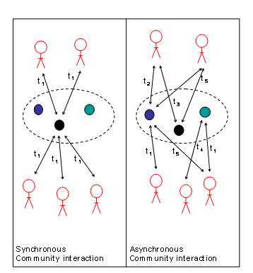
Figure 3‑20: Synchronous versus asynchronous
community interactions.
We now present a set of useful asynchronous and synchronous
community interaction features, able to fulfill tasks of features missed in
hosted resources or replace them. Synchronous features give tutors and students
the possibility to interact instantly together. The advantage lies in the
spontaneous nature of these features, which encourage direct communication and
prevent users from exchanging only well-prepared material as if it happens in
asynchronous features such as discussion boards. Examples of synchronous
features are video/audio conferencing,
chat, instant messaging, and white boards. Asynchronous features give tutors
and course subscribers the possibility to communicate in a time-shifted manner
and thereby to carefully prepare their statements, as involved persons do not
have to be online simultaneously. Examples of asynchronous features are discussion boards, calendars, pointers to web
pages, group announcements, frequently asked questions, meeting tools, Email,
and short message service.
The resource management portal includes basic community
interaction features for the management of users and hosted resources. Basic
community interaction features are necessary for the needed operations on users
and resources and include for example the building of resource lists or the
user notification functions. However, the resource management portal can do
more than just managing resources and users; it can offer enhanced features
such as discussion boards or chat. The most important point is that those
resources are personalized and fully manageable by portal administrators [Bg04].
One goal of the resource management portal is to integrate
easily new community management features. An implementation of the resource
management portal must offer an application-programming interface with at least
the possibilities to:
- Read user data from
the resource management portal database.
- Write user data into
the resource management portal database.
- Read resource data
from the resource management portal database.
- Write resource data
into the resource management portal database.
Figure
3‑21 shows the resource management portal, here connected
to Shibboleth as authentication and authorization infrastructure, together with
a document repository as connected resource. This Figure also shows that
community interaction features follow the same plug-in concept as resource
adaptors do. In the case that a resource owner would like to add a news board
to his or her resource, without changing the resource platform, which does not
foresee a news board, he asks the resource management portal administrator to
add a news board to the portal and the news board is ready to use.
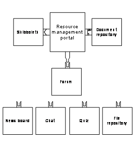
Figure 3‑21: Community interaction features.
Administrators see a list of built-in community management
features on the ‘My Resources’ page. It is possible to activate,
reactivate, or deactivate each built-in community management feature independently
for each resource. Each community management feature has a unique name and
displays additional information about its functionality.
The resource management portal is the entry point to the hosted
resources and all users must access the resource management portal before they
can access the resources. This position of the resource management portal makes
it a predestined place for accounting.
The term accounting has different
meanings in different areas. We limit our definition of accounting to the
requirements o f information and communications technologies. Accounting in
this area comprises the task of logging user and system activities for
security, billing, trend analysis, and auditing purposes.
A possibility would have been to
adapt existing accounting systems to the resource management portal. Systems,
which contain accounting and much more functionalities are for example Terminal
Access Controller Access Control System (TACACS) [Fc93], or the Remote
Authentication Dial-In User Service (RADIUS). All these existing solutions
bring more functionality and are thus too powerful for the accounting
requirements of the resource management portal.
The purpose of the accounting support on the resource
management portal is the data collection concerning the user actions done on
the resource management portal and not on the resources. These basic accounting
functionalities allow users of the resource management portal to visualize the
user behavior and to use the data for billing purposes and trend analysis. To
achieve this type of accounting we decided to design a proprietary accounting
schema.
A user activity in the resource management portal now starts
two processes, one results in the execution of the user request and the other
stores the relevant accounting data in a database. The accounting data must be
stored in the resource management portal’s database and no further
installation or configuration of external tools must be necessary. We have
decided to log all user actions done on the resource management portal, split
up into the existing user roles, discussed in Chapter 3.2.4 Actions users can perform on the portal are for
example: login, logout, change password, subscribe to a resource and unsubscribe
to a resource.
The users can visualize stored accounting data. Each user can
visualize its own data or the data of the users belonging to his or her
administrational area. The resource management portal administrator for example
can visualize the accounting data of all users.
Authorization Issues with Hierarchical Resources
The resource management portal must know which database
attributes a resource requires to handle correctly users accessing it. This is
a problem in “black box” resources where the internal functionality
of the resource is not documented. The resource management portal is hence not
able the generate user accounts in such resources split up in different user
roles. It is necessary to administrate such resources additionally and it can
be necessary for example to change manually the user roles within the resource
after the resource management portal has generated an account.
User Bob for example, future tutor of the resource, is
authenticated by its home organization, which provides all the necessary user
information attributes to enter the resource with different access levels as
shown in Figure
3‑22. This resource is a “black box” resource
and Bob’s account is generated as a default account with the
authorization to access level 1. At this level, Bob cannot select different sub
areas with higher restrictions without that an administrator of this resource
would manually upgrade his access levels to those corresponding to a tutor. In
an AAI-enabled resource, this would be no problem at all, as the user information
attributes could Bob identify as a tutor and the resource account automatically
be set to tutor by the resource itself.
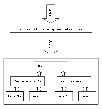
Figure 3‑22: Several authorization levels in resources.
Each user accessing the resource management portal can act in
different roles. We propose to implement at least three different user roles. These
user roles are not related to any other user roles described in this document
and only belong to the resource management portal. The users on the resource
management portal can be students accessing a hosted resource or administrators
administrating the portal. Additionally to these two user roles, we see the
need for a third user role: the administrator of one specific hosted resource,
which does not need to configure the entire portal and must not interfere with
other resources hosted on the portal. This leads to the three proposed user
role: The super user is the resource management portal administrator and
allowed to configure everything on the resource management portal. The second
user role is the resource administrator. He or she acts as owner of resources
hosted on the resource management portal. The third user role is the resource
user, sometimes simply called ‘user’. These are persons accessing resources
hosted on the resource management portal.
When users access the resource management portal, the
authentication and authorization infrastructure provides a set of reliable user
attributes. Those attributes serve to relate a user to a user role. In rare
cases, users access the resource management portal through the built-in direct
access interface. In this case, a portal administrator has to define manually
their user rights during the creation of the respective account.
We list the three proposed user roles below, together with
their specific functions:
User role 1: Resource users
Resource users are persons accessing the resource management
portal with the intention to access a hosted resource, for example students.
Their functionalities must be limited to subscribing and accessing subscribed
resources, community interaction tools, and visualization of own accounting
data as well as administrating their own user data stored on the portal. In
detail, resource users are able to:
- List all resources
visible to them.
- List the set of
already subscribed resources.
- List the set of
resources with pending subscription requests.
- Subscribe to and
unsubscribe from resources.
- View their attributes
the AAI has released to the resource management portal.
- Enter additional
required information (attributes) for specific resources.
- Administrate their
stored data.
- Define which
attributes are released to which resource.
- Access community
interaction features belonging to the subscribed resources.
- View own accounting
data.
- Close their account on
the resource management portal.
User role 2: Resource
administrators
Resource administrators are administrators of one or more
hosted resources on the resource management portal, for example tutors or
resource providers. Resource administrators may add or delete and fully manage
their resources and users belonging to these resources. In detail, resource
administrators are able to:
- Add and delete
resources.
- Own one or more
resources.
- Define how the
resource is integrated into the resource management portal by choosing the
resource adaptor.
- Define which way users
are redirected to the resource.
- Define which
attributes a resource user must provide for getting access to the
resource.
- Specify additional
(not yet existing) user information attributes on the portal.
- Define the
resource’s attribute acceptance policy.
- List their resources.
- List subscribed users
of these resources.
- View the information
their users provided to the resource management portal.
- Differentiate between
AAI and user provided attributes.
- Access the pending
subscription list of a resource.
- Accept or reject
subscription requests.
- Delete users at any
time from a resource.
- Suspend a user from a
resource.
- Suspend a resource.
- Release a notification
messages to users.
- Make resources visible
or invisible.
- Open or close
resources for subscription.
- Interlace subscription
to a manual selection.
- Add or delete users to
the resource management portal.
- View accounting data
about their resources.
- Add and delete
community interaction features prior installed by the portal administrator
to their resources.
User role 3: Resource
management portal administrator
Resource management portal administrators are able to do
anything resource administrators and resource users can do. Additionally,
resource management portal administrators are able to:
- Appoint resource
administrators.
- Initialize the
resource management portal.
- Add or remove
resources.
- Add or remove resource
administrators.
- Add or remove local
users.
- Specify short message
service gateway.
- Specify Email gateway.
- Install and remove
community interaction features.
- View global accounting
data.
- Export accounting
data.
- Integrate new resource
adaptors.
3.2.5 User
Interactions with the
Resource
Management Portal
In this Chapter, we present four out of many possible
time/action (interaction) diagrams for users of the resource management portal.
The first interaction
diagram shows a user who logs-in to the resource management portal as depicted in Figure 3‑23. Bob would like to login to the resource management
portal and so he opens a web browser where he enters the resource management
portal’s URL as shown in step 1. The resource management portal’s
AAI-enabled web server recognizes an unauthenticated user without credentials
and redirects this user in step 2 to the respective AAI services. The AAI
services together with Bob’s help redirect him to his home organization,
where the authentication process takes place. After Bob has been equipped with
credentials and security assertions in an opaque handle, he is redirected
again, this time back to the resource management portal as shown in step 3. The
resource management portal’s AAI components accept Bob and let him access
the entry page. The login process is now completed. Step 4 anticipates a
possible action Bob takes: he accesses a protected resource and is hence
redirected to it. Steps 2 and 3 are AAI-type specific.
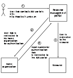
Figure 3‑23: Redirection processes to get to a
resource.
Resource providers who would like to open their protected
resources without having to maintain an own user administration have the
possibility to adapt their resource to each type of authentication and authorization
infrastructure in question or to adapt their resource only once to the resource
management portal. The resource management portal administrator adds the
resource owner to the resource management portal users in the role of a
resource administrator.
Figure
3‑24 shows the UML use case diagram for the process of
hosting a new protected resource to the resource management portal. The
resource owner applies for the hosting of the resource on the portal with the
resource management portal administrator. The portal administrator approves or
rejects the application. In the case of an approval, the resource owner becomes
a resource administrator on the portal and thereby gets the possibility to add
his or her resource to the resource management portal. The portal administrator
manages the resource adaptors and if necessary, installs a new adaptor for the
new resource. Upon a successful installation, the resource owner configures his
or her resource and opens it for subscription. The newly added resource is
advertised at the resource management portal’s entry page as recently
added resource. The resource administrator manages the now operational
resource. In case the resource owner decides to enable access control for the
resource, he or she has to admit access to each applying user. Misbehaving
users have to be unsubscribed or their access suspended, for example if they do
not pay their utilization fee. If the resource administrator needs local user accounts
for users without AAI accounts, the portal administrator registers these users
upon request locally.
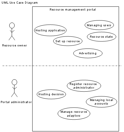
Figure 3‑24: UML use case diagram for resource hosting.
Figure
3‑25 shows the UML use case diagram for the interactions
between user Bob and the resource management portal when Bob tries to subscribe
to a resource. In a first step, Bob has to access the resource management
portal and go through the above described authentication process. After that,
he gets to the resource management portal’s entry page and can access a
list of all hosted resources. Bob now chooses a resource and after reading the
information about the resource and its owner, decides to subscribe to the resource
in the form of a resource subscription request. The resource management portal
now requests missing user information attributes resulting from the difference
between the user’s attribute release policy and the resource
owner’s attribute acceptance policy. If the resource is open and freely
accessible to all authentication and authorization infrastructure users, he now
is redirected to the resource. If there is a list for pending subscriptions,
Bob has to wait until a resource administrator accepts or rejects his subscription
request. Upon this action, Bob receives a status change message by Email or
short message service. The resource administrator comes to a decision and
accepts or rejects the user. It is possible to reject a subscribed user later
and to temporarily suspend or resume a user.
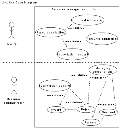
Figure 3‑25: UML use case diagram for resource
subscription.
This Chapter discusses the prototypically implemented resource
management portal architecture. It describes the implemented adaptors for
authentication and authorization infrastructures and resources as well as the
database design and the web interfaces. At the end of our work, we gave the
code to an organization for an ongoing and professional code management. We
have chosen to write the implementation in PHP and to use a MySQL database. We
published the code under the General Public License (GPL).
Figure
3‑26 shows the entry page for a resource management portal
user in the portal version 0.9.3. All already subscribed resources appear on
top whereas the recently added resources are below. The navigation tools are on
the left side.
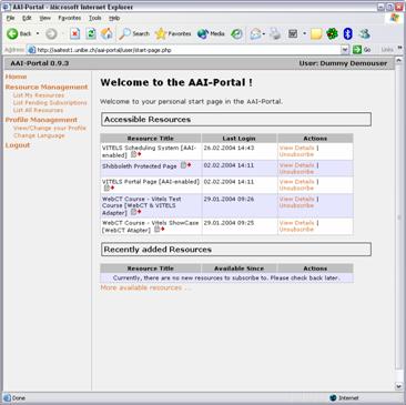
Figure 3‑26: Resource management portal’s web interface.
The prototypical implementation of
the resource management portal comprises an adaptor to Shibboleth as a
particular authentication and authorization infrastructure. However, it is
possible to connect most authentication and authorization infrastructure to the
resource management portal, if they fulfill two preconditions:
1)
The authentication and authorization infrastructure
must HTTP-redirect users to a redirect target consisting of an entry point in
the resource management portal.
2)
For an administrative-friendly functioning, the
request for accessing the resource management portal must be accompanied by a
set of user information attributes. The only necessary user information
attribute is the unique user name @ home organization. Other user information attributes
must be specifically mapped to resource management portal internal attributes.
The only implemented adaptor to an
authentication and authorization infrastructure is to Shibboleth. For a successful
combination of the resource management portal with Shibboleth, it is necessary
to install the Shibboleth target site code on the same server as the resource
management portal resides. In addition, the web application container such as
Apache in our case, which hosts the resource management portal, must be
integrated with the Shibboleth target site software accordingly to the
Shibboleth installation guide.
It is necessary to configure the web
application container such that users must authenticate with Shibboleth when
they access one of these entry points. Usually, web application containers
offer multiple configuration options to restrict access to a specific page. If
Apache is the web application container, the respective configuration entries go
to the common Apache configuration file (httpd.conf) or in an access control
file written to the directory, which has to be protected (.htaccess). The resource
management portal’s software package ships with sample .htaccess files in
the directories, containing the two entry points, which look similar to the
example in Figure 3‑27:
#
#.htaccess
- sample access control file for Resource management portal entry point
#enable
Shibboleth authentication
#
AuthType
shibboleth
ShibExportAssertion
On
require
valid-user
#
Figure 3‑27: Resource management portals’ sample
.htaccess file.
Users authenticated in the Swiss
Shibboleth implementation have a unique identity provided in the attribute
swissEduPersonUniqueID (encrypted user name @ home organization). A set of
additional 24 attributes has been defined, six of which (including swissEDUPersonUniqueID)
are required. The two resource management portal entry points receive specific
attribute values in HTTP headers reserved for this purpose. They map these
attributes to attributes used within the resource management portal and cache
them in the resource management portal’s database.
In the resource management portal, a
resource adaptor consists of PHP code, which is responsible for redirecting a
user from the resource management portal to an external resource. The resource
management portal design allows the deployment of any number of resource
adaptors in a resource management portal installation, because resource
adaptors conform to a kind of plug-in specification. This ensures that it is
possible to disable and replace resource adaptors and that new custom adaptors
can be developed and installed easily.
The developer of a resource adaptor
has to implement at least an adaptor PHP page and to provide an adaptor
descriptor. The adaptor PHP page is an isolated PHP page, which goes to the
directory aai-portal/adapters. The page must accept a single resource identity
in the request parameter rid. It must also ensure that the current session is a
valid resource management portal session. Given the current user and the
resource identity, the adaptor PHP page must prepare access to the remote
resource and redirect the user to the target URL. The execution of an adaptor
PHP page hence usually finishes with emitting a HTTP-redirect header.
The adaptor descriptor consists of a
set of configuration parameters. Each resource adaptor has a unique identity
and an array of name/value pairs. It is possible to configure the following properties
for a resource adaptor:
- display-name (optional):
The adaptor’s display name to be used in web interfaces widgets like drop-down lists. If missing, the adaptor identity is used instead. - adaptor-file (required):
The relative URL to the resource adaptor implementation. The URL is relative to the PORTAL_BASE_URL (as defined in the aai-portal.config file of the installation). - help-text (optional)
An optional help text explaining the functionality of the resource adaptor and the resources it fits to. - parameters (optional):
An optional list of resource adaptor parameters such as the shared secret or the password used to login users in the target resource.
- Each resource adaptor may specify a list of additional resource
adaptor parameters in the property 'parameters'. A resource parameter is
an information item the resource owner must enter when he or she
configures a resource adaptor for a specific resource.
Resource adaptor descriptors are
stored in the global configuration file config/adapters.config. This
configuration file declares an array of resource adaptor descriptors using
standard PHP syntax; actually, the configuration file will be loaded using a
call to require_once(...). Therefore, any kind of PHP literals, i.e. numeric
literals like 999 or 123.45, string literals like "test" or 'test',
etc. can be used. Key/value pairs have the form key => value.
The prototype implementation supports
the below listed resource adaptors:
Simple HTTP-redirection
The simple HTTP-redirection adaptor redirects the user to the target URL. This adaptor is useful for
integrating non-protected resources into the list of resource management portal
resources. An example of such a resource could be the main site of a university
where the portal is located.
HMAC-based authentication
This resource adaptor generates and
writes a cookie into the user’s browser, which authenticates the user at
the target resource. The resource adaptor HTTP-redirects the user. The cookie
includes the unique user identity and additional user information attributes,
specified in the web interface. The cookie is subjected to a keyed hash
according the HMAC generation discussed in RFC 2104 (HMAC:
Keyed-Hashing for Message Authentication). The shared secret must be known by
the resource management portal as well as to the target resource. This adaptor
is fine for a redirection to resources running in the same domain as the portal
due to the problems caused by third party cookies.
WebCT Adaptor
This resource adaptor HTTP-redirects
resource management portal users to a course home page hosted on a WebCT 4.x
server. The WebCT adaptor provisions the WebCT user database and does an
automatic sign on for the user. The resource adaptor verifies if a user already
possess a WebCT identity in the resource managements database. If not, this
identity is generated. The resource adaptor and WebCT possess two shared
secrets. The resource adaptor now sends the login parameters to the WebCT
application-programming interface for adding and enlisting users in the course
specified in the resource adaptor settings before. The data is protected with
the first shared secret. The second shared secret serves to encrypt the login
data posted in the URL of the HTTP-redirection.
Computer Networks
Laboratory Adaptor
This resource adaptor adds resource
management portal users to the resource management system’s LDAP database
and HTTP-redirects resource management portal users to pages such as the
scheduling system or a laboratory portal. The resource adaptor possess read and
write access in the LDAP database, i.e. a user name and a password to perform
the mutations.
Computer Networks
Laboratory Adaptor and WebCT Adaptor
A combination of the before described
WebCT and computer networks laboratory adaptors is also integrated. The
combination of these two resource adaptors allows logging-in students to the
WebCT course and directly connecting out from there to the scheduling system or
laboratory portals.
3.3.4 Web Application with a Database Backend
The resource management portal potentially offers access to
resources for users who originate from different language regions. The resource
management portal should adapt user interfaces to the language attribute users
provide via the authentication and authorization infrastructure and otherwise
offer the possibility to switch manually between languages. We propose to use
the I18N internationalization scheme [I18N and Ws98].
Figure
3‑28 show a system diagram of the resource management
portal. The resource management portal is a web application with web interfaces
for users and administrators and a database.
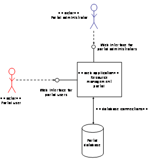
Figure 3‑28: Resource management portal’s system diagram.
The resource management portal’s database consists of
nine SQL tables:
User: The user table holds the
unique user id (User_uid) which must be provided by the authentication and
authorization infrastructure or by the process adding local users. Each entry
must have a privilege level from the UserPrivilege table.
Accounting: The accounting table
holds the accounting data for each user.
UserPrivilege: The UserPrivilege table
has three standard entries, a normal user privilege (student), a resource
administrator privilege, and a portal administration privilege. It serves to
distinguish normal users from administrators.
Attribute: This table holds the
attribute value for one specific attribute. Each user can have any number of
attributes and each attribute must have exactly one AttributeType.
AttributeType: Each attribute value must
have a type. These types are stored in this table and it is initialized with
the standard authentication and authorization infrastructure attributes but it
can also be extended by custom, string encoded attribute types.
Resource: The resource table stores
the properties for each resource. Each resource entry must have exactly one
user with at least resource administrator privilege.
Policy: This table defines which
AttributeTypes are necessary for each resource; technically, it is a relation
between the resource and the AttributeType table.
ResourceAdapterParam: This table holds
configuration parameters for resource adaptors.
Subscription: The subscription table
connects a user table entry to a resource. Like the policy table it is a
relation between two other tables, user and resource. It holds some additional
data like access control information.
Figure
3‑29 shows a diagram depicting the resource management
portal’s database schema.
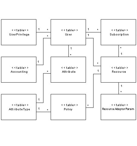
Figure 3‑29: UML class diagram for the resource
management portal’s database.
The main goal of the measurements presented and discussed in
this section is to provide an approximate user access rate (how many users in a
certain time) to a resource management portal installation on a certain type of
hardware, related to CPU and RAM capacity. A further goal is to find out, which
of the applications limit this rate, the Apache web server, the MySQL database
or any other. We do not intend to measure any login delays caused by eventually
connected authentication and authorization infrastructures, as we are not
interested in the performance of third party systems such as Shibboleth.
Therefore, we use the resource management portal’s local web interfaces
for login procedures.
3.4.1 Measurement Scenarios and Methods
The measurement testbed consisted of two different resource
management portal installations (only one was in use at once), five clients,
and a web server, as depicted in Figure
3‑30. We installed the two resource management portals on
a Pentium 2 300 MHz with 512 Mega Bytes of RAM and on a Celeron 1 GHz with 256
Mega Bytes of RAM machines.
We used the resource management portal software version 0.9.5
for both of the installations. The resource web page of the external web
resource, hosted on the resource management portal and used in the second part
of the measurements run on a Pentium 4, 2.8 GHz with 2 Giga Bytes of RAM
machine and the served web page had the size of 122 Bytes. All servers were
running Red Hat Linux version 7.2 with and out of the box configuration.
We installed the performance measurement tool JMeter version
2.0.1 [Hr01] on five Pentium 3 800 MHz with 384 Mega Bytes of RAM machines,
running Windows 2000, and used to generate and analyze HTTP-requests to the
resource management portals’ web server. It is possible to write
measurement scripts for JMeter. JMeter can thus perform multiple queries and
actions on web server, id est, it can retrieve web pages, login if necessary by
sending user name and password, retrieve and send cookies and more. The
performed measurements each consisted of single measurement events. A
measurement event for example is a login into the resource management portal
and a HTTP-redirection to the external web pages. Each JMeter client processed
only one event at once and proceeded to the next only after finishing the fore
one. With five clients, a maximum of five events can simultaneously be running.
To make the measurements closer to real life scenarios, we
performed two different measurements. In both, we used all the five client
machines to generate simultaneous HTTP-requests to the resource management
portal. In the first measurement series they logged-in and retrieved an
internal resource information page whereas in the second series they logged-in
and accessed an HTTP-redirection link to the resource’s web server. Two
kinds of measurements have been performed in each of the two settings. In the
first, the five clients generated as many HTTP-requests as possible. This
stress measurement was used to calculate the maximal event rate of accesses per
second. In the second, the five clients increased the HTTP-request rate
successively, starting with a low rate. They should access the portal a certain
times per minute but used more than a minute per step if the portal was too
slow. This measurement ended up in a stress measurement too.
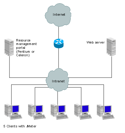
Figure 3‑30:
Performance measurement testbed.
On the resource management portal, we logged the CPU and memory
load for the Apache web server, the MySQL database and the system. For this
purpose we started the program top [FS02] and logged the statistics comprising
of CPU load per process and memory usage every 5 seconds.
The hardware selection is of crucial nature in the succeeded
stress measurements. We thus installed both resource management portals on the
slowest machines used in the testbed and the clients and the resource’s
web server on faster machines. Thereby it is possible to guarantee that the
JMeter clients can load the resource management portal up to its maximum
capacity. The fastest machine used was the resource’s web server. This
machine should not bring a delay in the measurements and thus only served the
smallest possible HTTP page. Additionally, five querying JMeter clients increase
the events rate by five and guarantee that the resource management
portal’s limits can be reached. In the case where we measured the user
redirection to the resource’s web server, we used the simple
HTTP-redirection adaptor, which is the simplest and thus the fastest one of all
imaginable adaptors. The adaptor only makes a lookup in the database for the
redirection URL. With this adaptor, we can exclude redirection delays due to
access operations on the resource’s web server.
3.4.2
Access of a Resource Information Page on
the Resource Management Portal
1)
For each of the five client
machines, a unique resource management portal user was generated.
2)
Each client user then
accessed the resource management portal.
3)
The user logged-in through
the local user web interface.
4)
The clients received a
cookie with the log-in information.
5)
The users retrieved the resource’s
information page on the portal itself.
Full Access Stress Measurement
In the first measurement of this experiment, the five users accessed the
portal at full query capacity for measuring the maximum access rate in events
per seconds. An event consists of the log-in to the portal and the retrieval of
the internal resource information page, resulting in two requests.
Figure 3‑31 and Figure 3‑32 show the access rate charts of the 300 MHz and 1 GHz
portals, respectively. 0.53 and 1.84 events as well as rates of 1.06 and 3.68 requests
per second could be achieved. Both graphs show constant rates over the full
measuring time. As each client can only send the next request when the prior
one was finished, we expected this behaviour. Nevertheless, this measurement
revealed the maximum access rates possible in this setting. We used these
results for a comparison of the achieved rates in the experiments of with
increasing access rates.
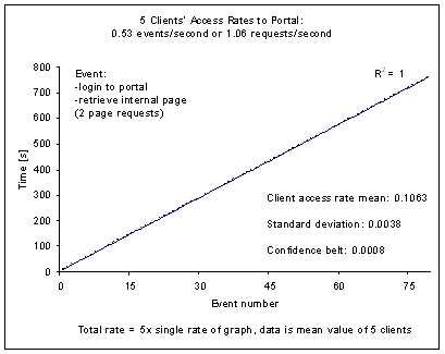
Figure 3‑31: Full
access, 300 MHz, internal page.
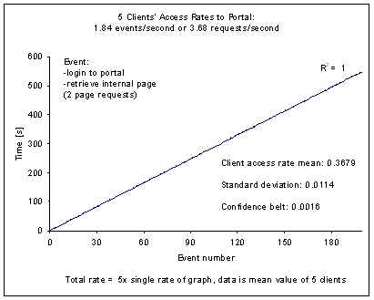
Figure 3‑32: Full
access, 1 GHz, internal page.
Figure 3‑33 and Figure 3‑34 show the CPU usage of the 300 MHz and 1 GHz portals,
respectively. They oscillated around 95 to 100%, the user around 90 to 95 % and
the system around 5 to 8%, and around 94 to 100%, the user around 81 to 87% and
the system around 13 to 18%, respectively. In both portals, the CPU was fully
busy during the measurements. Also in both portals, the user processes took the
remaining CPU power, which was not used by the system. The higher system CPU usage
in the faster portal is due to the higher access rates, which required more
system power, for example for managing the network interface and the input
output system.
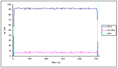
Figure 3‑33: CPU
load full access, 300 MHz, internal page.
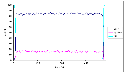
Figure 3‑34: CPU
load full access, 1 GHz, internal page.
Figure 3‑35 and Figure 3‑36 show the CPU load for the Apache and the MySQL
daemons, which oscillated around 59 to 64% and 0 to 7 %, and 75 to 82% and 0 to
2%, respectively. Both portals show that the MySQL database consumes few CPU
power but also that the Apache daemon claims as much power as possible. Already
here we can see that we could improve the access rates by improving the Apache
configuration instead of using the out of the box settings. The dynamic PHP web
pages are prepared in the Apache und thus consume the CPU power.
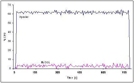
Figure 3‑35: Apache &
MySQL CPU load full access, 300 MHz, internal page.
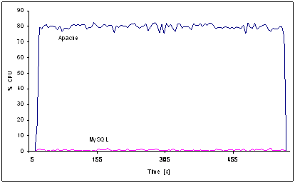
Figure 3‑36: Apache &
MySQL CPU load full access, 1 GHz, internal page.
Figure 3‑37 and Figure 3‑38 show the memory load during the measurement. The 300
MHz machine used 304.3 MB at the beginning and remained at around 305.7 MB from
sample 157 on. The 1 GHz machine used 180.9 MB at the beginning and remained at
around 192.6 MB from sample 113 on. The slight increase of memory consumption
is due to a reallocation of the memory during the measurement. As above
discussed, the faster portal consumes more CPU power and also more memory for
coping with the higher access rates.
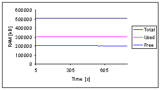
Figure 3‑37: Memory
load full access, 300 MHz, internal page.
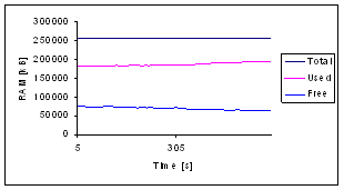
Figure 3‑38: Memory load full access, 1 GHz, internal page.
Increasing Access Stress Measurement
In the second experiment, the access traffic was increased, starting
with 50 accesses and then increasing to 75, 100, 500 and 1,000 accesses in 60
seconds, each. If possible, the accesses should have been performed in 60
seconds; else, the next level was begun only after finishing the prior. The
maximum capacity was reached when the rate met the rate of the full access
measurement discussed before. Different
to the prior ones, these measurements showed how many events can be performed
per minute and showed the respective process and memory load during the
increasing load.
Figure 3‑39 and Figure 3‑40 show the charts of the 300 MHz and 1 GHz portal,
respectively. The graphs show a slight bend at the beginning, indicating a
lower access rate due to the slow starting JMeter client queries. During the
measurement, both portals reach their maximum capacity, which is exactly the
same as in the full access measurements.
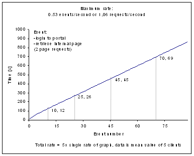
Figure 3‑39:
Increasing access, 300 MHz, internal page.
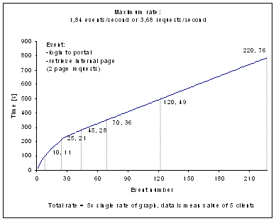
Figure 3‑40:
Increasing access, 1 GHz, internal page.
Figure 3‑41 and Figure 3‑42 magnify the first part of the graphs in Figure 3‑39 and Figure 3‑40, respectively. The graphs show where the
portal’s events rate capacity was exceeded and the requests were queued.
At the beginning of the graphs, each client request was fully processed before
a new one arrived. With time, the clients’ access rates have been increased
as mentioned initially and the portals could no more process all the queries
from the five JMeter clients within the specified time span. The slower portals
capacity exceeds in the second access level, whereas the faster portal
reallocates system resources and manages to increase its capacity. The maximum
access rate of the faster portal is only reached in the third access level of
the measurement series.
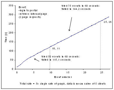
Figure 3‑41: Detail
of increasing access, 300 MHz, internal page.
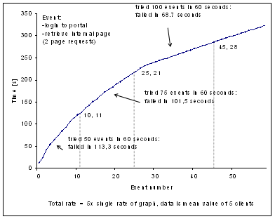
Figure 3‑42: Detail
of increasing access, 1 GHz, internal page.
Figure 3‑43 and Figure
3‑44 show the CPU usage during the first part of the
measurements of the 300 MHz and 1 GHz portal, respectively. They oscillated
around 51 to 68% for the user and 3 to 5% for the system during the 5 first
events and took 65 seconds on the 300 MHz machine. In step 6, the CPU usage
increased to the same load as found in the measurement with full access. On the
1 GHz machine, the CPU usage oscillated around 10 to 19% for the user and 0 to
5% for the system during event 1 to 3, around 18 to 30% for the user and 4 to
6% for the system during event 5 to 10, around 39 to 59% for the user and 5 to
8% for the system during event 11 to 18, around 32 to 47% for the user and 6 to
9% for the system during event 19 to 25, around 76 to 78% for the user and 12
to 16% for the system during event 26 to 51, and increased to the same CPU load
as in the full access in step 52. Both graphs show how the system idle
decreases, whereas user and system CPU power increase. The peaks show the
access events of the five JMeter clients, which have been started
synchronously. The increase of the system power consumption also shows that not
only user processes are responsible for the processing of the requests but also
the IO system.
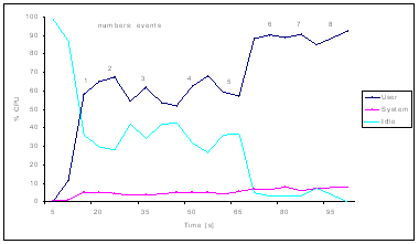
Figure 3‑43: CPU
load of detail of increasing access, 300 MHz, internal page.
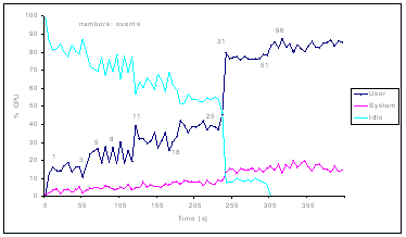
Figure 3‑44: CPU
load of detail of increasing access, 1 GHz, internal page.
Figure 3‑45 and Figure 3‑46 show the CPU load for the Apache and MySQL daemons in
this first part of the measurements of the 300 MHz and 1 GHz portal, respectively.
They oscillated around 34 to 44% for the Apache and around 0 to 5% for the
MySQL daemon during the first 5 events on the 300 MHz machine. In step 6 the
CPU load increased to the same rate as in the full access measurement. On the 1
GHz machine, the CPU usage oscillated around 9 to 16% for the Apache and 0 to
1% for the MySQL daemon during event 1 to 3, around 15 to 26% for the Apache
and 0 to 1% for the MySQL daemon during event 5 to 10, around 22 to 33% for the
Apache and 0 to 1% for the MySQL daemon during event 11 to 18, around 34 to 38%
for the Apache and 0 to 1% for the MySQL daemon during event 19 to 25, around
70 to 75% for the Apache and 0 to 1% for the MySQL daemon during event 26 to
51, and increased to the same CPU load as in the full access in step 52.
Particularly in the slower portal the coincidence of system MySQL and Apache
daemon CPU usage is well visible. Each event made over the web interface
resulted in a lookup for the user data and a lookup for the resource information
page.
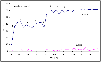
Figure 3‑45: Apache &
MySQL CPU load of detail of increasing access, 300 MHz, internal page.
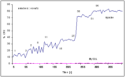
Figure 3‑46: Apache &
MySQL CPU load of detail of increasing access, 1 GHz, internal page.
Figure 3‑47 and Figure 3‑48 show the memory load during the measurement. The 300
MHz machine used 305.7 MB at the beginning and remained at around 307.6 MB from
sample 176 on. The 1 GHz machine used 150.3 MB at the beginning and remained at
around 163.7 MB from sample 161 on. Again, both machines reallocated their
system resources and adapted them to the actual requirements. For improving the
portals capacity they should be configured as web servers and not be used with
out of the box settings.
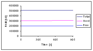
Figure 3‑47: Memory
load of increasing access with 300 MHz, internal page.
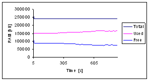
Figure 3‑48: Memory load of increasing access with 1 GHz, internal page.
3.4.3
Access of an External Resource Management
Portal Hosted Resource
In this measurement, the portal’s capacity of
letting users log-in and HTTP-redirecting to a resource’s web server was
measured. Each of the five client machines used a unique resource management
portal user. The resource’s web server was located in the same Intranet
as the portal and the clients as shown in Figure 3‑30.
This measurement is close the real life scenarios,
where users login to the resource management portal and then directly click on
a subscribed resource for accessing it. This HTTP-redirection URL was provided
by the simplest resource adaptor, which redirects users to web sites with no
access control mechanisms. The measurement consisted of the following steps:
1)
For each of the five client
machines, a unique resource management portal user was generated.
2)
The users accessed the
resource management portal, logged-in through the local user web interface.
3)
The clients received a
cookie with the log-in information.
4)
The users then accessed a
resource’s HTTP-redirection URL on the portal itself.
5)
The clients retrieved the
resource’s web page.
Full Access Stress Measurement
In the first measurement, the five users accessed the
portal at full capacity for measuring the maximum access rate in events per
seconds. This is the same procedure as described in above. An event consists of
the login to the portal and the HTTP-redirection to the resource’s web
site, resulting in a total of two requests.
Figure 3‑49 and Figure 3‑50 show the access rate charts of the 300 MHz and 1 GHz
portal, respectively. 1.06 and .3.42 events as well as rates of 2.12 and 6.84 requests
per second could be achieved. These maximum events are higher as in the
measurements with an internal page access (0.53 and 1.84; 1.06 and 3.68). This
is a result of the HTTP-redirection in the second step of the access procedure.
Instead of retrieving the internal resource information page, which also
requires a database lookup, the user gets directly redirected to the
resource’s web server. Figure 3‑50 shows a regression, which is not 1 but 0.9995. The
single values of this measurement show that the access rates increases with
time before it stabilizes again. IT is not clear what caused this irregularity
as the test bed settings were identical with the other three access rate
measurements.
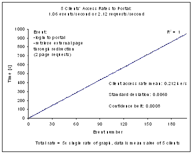
Figure 3‑49: Full access with 300 MHz, external page.
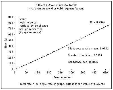
Figure 3‑50: Full access with 1 GHz, external page.
Figure 3‑51 and Figure 3‑52 show the CPU usage during the measurements of the 300
MHz and 1 GHz portal, respectively. They oscillated around 93 to 100%, the user
around 90 to 96% and the system around 3 to 10%, and around 94 to 100%, the
user around 81 to 87% and the system around 13 to 18%. The CPU was used at its
maximum capacity. This shows that the portals were both operating at their
maximum capacity and also excludes the possibility that the resource’s
web server is the bottle neck in this measurement. The slight higher system CPU
load of the faster portal is a result of the higher access rate, which requires
more power for the system’s IO system.
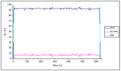
Figure 3‑51: CPU load during full access with 300 MHz,
external page.
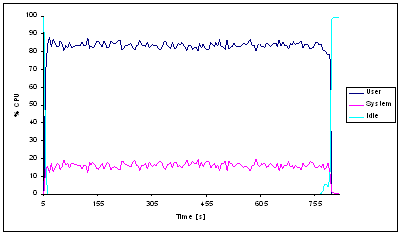
Figure 3‑52: CPU load during full access with 1 GHz,
external page.
Figure 3‑53 and Figure 3‑54 show the CPU load of the Apache and MySQL daemons of
the 300 MHz and 1 GHz portal, respectively. They oscillated around 56 to 64%
and 0 to 7 %, and 75 to 83% and 0 to 2%, respectively. The Apache daemon uses
the main part of the CPU load whereas the database lookup consumes little
power. This is almost the same division as in the same measurement in Chapter 3.4.2 (59 to 64% and 0 to 7%; 75 to 82% and 0 to 2%).
Instead of providing an internal resource information page, the portal in this
measurement provides the HTTP-redirection link directly after the user login.
This explains the same CPU load in both experiments and the higher access rates
in the latter.
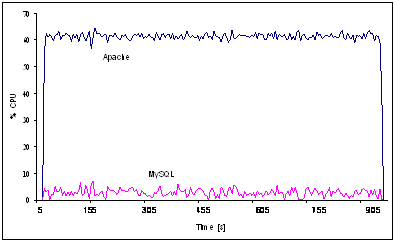
Figure 3‑53: Apache & MySQL CPU load, full access
with 300 MHz, external page.
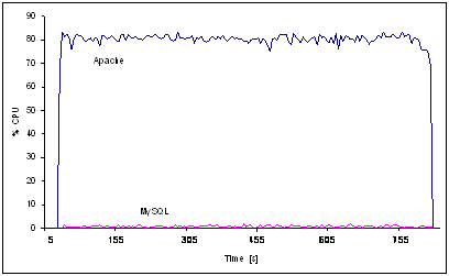
Figure 3‑54: Apache & MySQL CPU load, full access
with 1 GHz, external page.
Figure 3‑55 and Figure 3‑56 show the memory load during the measurement. The 300
MHz machine used 302.5 MB at the beginning and remained at around 304.2 MB from
sample 192 on. The 1’000 MHz machine used 163.8 MB at the beginning and
remained at around 180.8 MB from sample 164 on. Here too we see a resource
reallocation from the system during the stress measurement. This behaviour also
shows that systems with more memory and CPU capacity can process more queries.
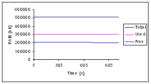
Figure 3‑55: Memory load, full access with 300 MHz,
external page.
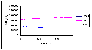
Figure 3‑56: Memory load, full access with 1 GHz, external page.
Increasing Access Stress Measurement
In the second part of this
experiment, the access traffic was increased, starting with 50 accesses in 50
seconds and then increased to 75, 100, 500 and 1000 accesses in 60 seconds. If
possible, the accesses should have been performed in 60 seconds; else, the next
level was begun only after finishing the prior. The maximum capacity was
reached when the rate met the rate of the full access measurement discussed
above.
Figure 3‑57 and Figure 3‑58 show the charts of the 300 MHz and 1 GHz portal,
respectively. 1.06 and 3.42 events as well as rates of 2.12 and 6.84 requests
per second could be achieved. These are the same values as in the full access
measurement. Only at the beginning a slight bend is visible. This is due to the
low access rates at the beginning executed by the JMeter clients.
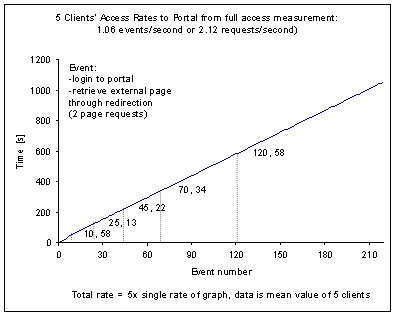
Figure 3‑57: Increasing access with 300 MHz, external
page.
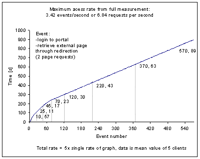
Figure 3‑58: Increasing access with 1 GHz, external
page.
Figure 3‑59 and Figure 3‑60 show the first part of Figure 3‑57 and Figure 3‑58 where the portal’s capacity was exceeded.
Compared to the access to the resource information page hosted on the portal of
Chapter 3.4.2 (0.53 and 1.84; 1.06 and 3.68) the access rates are
more or less doubled. The magnifications of both plots show in detail how the
portals manage the access traffic and when the access rates exceed the
capacity.
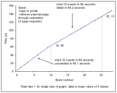
Figure 3‑59: Detail of increasing access with 300 MHz,
external page.
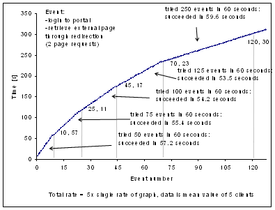
Figure 3‑60: Detail of increasing access with 1 GHz,
external page.
Figure 3‑61 and Figure 3‑62 show the CPU usage of the 300 MHz and 1 GHz portal during
the first part of the measurements, which oscillate around 83 to 69% for the
user and 3 to 7% for the system during the 11 first events and took 65 seconds
on the 300 MHz machine. In step 12, the CPU usage increased to the same load as
found in the measurement with full access. On the 1’000 MHz machine, the
CPU usage oscillated around 10 to 19% for the user and 0 to 5% for the system
during event 1 to 10, around 24 to 39% for the user and 4 to 8% for the system
during event 11 to 25, around 33 to 41% for the user and 5 to 9% for the system
during event 26 to 45, around 42 to 55% for the user and 7 to 12% for the
system during event 46 to 70, and increased to the same CPU load as in the full
access in step 71. The correlation of the peaks in the user and idle graphs is
visible and the increase of the access rates is reflected in an increase of the
system CPU usage. In the faster portal much access rates steps are visible due
to its higher capacity.
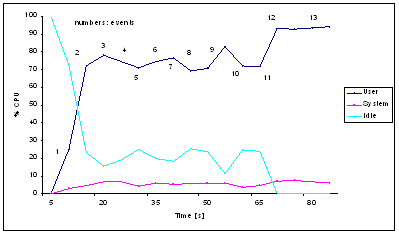
Figure 3‑61: CPU load of detail of increasing access
with 300 MHz, external page.
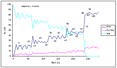
Figure 3‑62: CPU load during detail of increasing access
with 1 GHz, external page.
Figure 3‑63 and Figure 3‑64 show the CPU load of the Apache and MySQL daemons in
this first part of the measurements of the 300 MHz and 1 GHz portal. They
oscillated around 42 to 52% for the Apache and around 0 to 5% for the MySQL
daemon during the first 11 events on the 300 MHz machine. In step 12 the CPU
load increased to the same rate as in the full access measurement. On the
1’000 MHz machine, the CPU usage oscillated around 11 to 20% for the
Apache and 0 to 1% for the MySQL daemon during event 1 to 10, around 22 to 36%
for the Apache and 0 to 1% for the MySQL daemon during event 11 to 25, around
32 to 38% for the Apache and 0 to 1% for the MySQL daemon during event 26 to
45, around 40 to 50% for the Apache and 0 to 1% for the MySQL daemon during
event 46 to 70, and increased to the same CPU load as in the full access in
step 71. The correlation between Apache and MySQL daemons is visible. It is
also visible that the MySQL daemon’s peaks are slightly delayed to the
Apache’s peaks. This can be explained by the fact that users first access
the web server, which then uses the database for the user lookup.
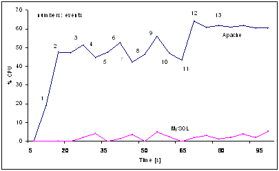
Figure 3‑63: Apache & MySQL CPU load of detail of
increasing access
with 300 MHz, external page.
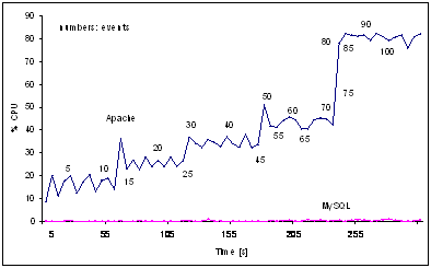
Figure 3‑64: Apache & MySQL CPU load of detail of
increasing access
with 1 GHz, external page.
Figure 3‑65 and Figure 3‑66 show the memory load during the measurement. The 300
MHz machine used 309.8 MB at the beginning and remained at around 311.0 MB from
sample 201 on. The 1 GHz machine used 192.6 MB at the beginning and remained at
around 209.1 MB from sample 216 on. As in the prior measurements a memory
reallocation during the measurements can be observed. This is a normal
behaviour of the system. The performance can be increased by configuring the
system as a web server acting as a web front end with a database.
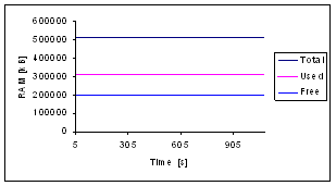
Figure 3‑65: Memory load of increasing access with 300
MHz, external page.
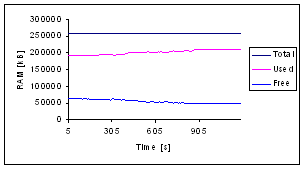
Figure 3‑66: Memory of increasing access with 1 GHz, external page.
3.4.4 Measurement Summary
The performance measurements showed stable event/access (one
events consists of two accesses) rates in the full access measurements for both
machines, the 300 MHz with 0.53 events per second / 106 accesses per second
with the second access to an internal resource information page or 1.06/2.12
and 1 GHz with 1.84/3.68 with the second access to an HTTP-redirection URL
leading to resource web page or 3.30 or 6.60. The faster rate for accessing the
resource’s web page originate from less work load by the HTTP-redirection
than by serving an internal PHP resource information page. In none of the
measurements, the MySQL daemon caused much CPU load, up to 7% for the 300 MHz
and 2% for the 1 GHz machine. All the available CPU power, which was not
consumed by the system or MySQL daemon, was consumed by the Apache daemon.
The limitation to a maximum of five parallel client accesses
prevented an endless growth of the TCP queues and the memory consumption
reached a stable point in each measurement. Five clients do not reflect real
life conditions where much more clients could access the system, but the
clients were constantly and break less accessing the portal, which would not be
the case with human users. Most e-learning resources in
There are potential software bottlenecks in the implementation:
The web server with the dynamic PHP pages and its configuration are important,
as the web server is the daemon, which consumes all the available CPU power.
The same conclusions as for other web servers apply for increasing the
performance [BD97]. The operating system itself could be another bottleneck.
The operating system manages the CPU access, memory usage, and input/output of
data.
3.5 Discussion and Conclusions
The resource management portal architecture fulfills the
requirements for implementations of brokers between resources and user
management systems. It is also possible to use the implementations for
standalone operation. The architecture firstly focuses on the management of
resources, hosted on the resource management portal. Resource owners get a
palette of useful features for their hosted resources. They may open or close
the resource for subscription, open or close the resource access for single
users or groups of users, request user information from users and send Email or
short messages to users and groups of users. These resource functionalities
provide resource owners the possibility to connect before unprotected
resources, for example running on an Apache web server, in few steps to the resource
management portal and get a protected resource. The second focus of the
architecture concerns user management. Resource users may view resource information
pages and subscribe or unsubscribe to resources. Resource administrators manage
their resources and grant or deny access to resource users. Portal administrators
manage the resource administrators and local user accounts. All these user functionalities
ease resource access for resource users. Both, user and resource management
functionalities form a set of features, which are useful for the operation, and
the access of resources. The architecture focuses additionally on two other
areas: Inter-user communications and accounting. Inter-user communication is a
necessary feature for user communities such as classes of students. Examples
for such features are discussion boards or document stores. The architecture
foresees that each features belongs to on hosted resource and that users of the
resource management portal obtain the same roles in these features as on the
portal. Accounting functionalities visualize the user behavior and build the
base of billing models. The architecture foresees modular plug-ins for the
connection of user management systems, resources and user communication
features. With these bricks, it is possible to achieve low production costs and
high reusability effects.
The succeeded implementation of the resource management portal
realizes the architecture in PHP and MySQL. Using the popular programming
language and database resource owners and portal operators can adapt existing
or implement new resource adaptors. The plug-in concept also simplifies the
integration of communication features or the enhancement of the portal code. We
successfully implemented the adaptor to the user management system Shibboleth,
an Internet2 initiative. We also implemented several resource adaptors, for
example to the described computer networks laboratory.
The performance measurements helped for estimating the required
system capacity for using the resource management portal in production. We
discussed the details of the measurements in the measurement section. We could
confirm our expectations with those results. The web server consumes most of
the system’s power for the preparation of the dynamic web pages and the
database with the system together use little capacity. The software is able to
manage thousands of users when installed on state-of-the-art servers, optimized
for serving dynamic web pages.
We handed over the resource management portal project to SWITCH
for a further development and for the maintenance of the code. This undermines
the usefulness of the developed architecture and its first implementation. The
portal is one of several ways to connect resources to the Swiss-authentication
and authorization infrastructure Shibboleth. The document [SSBB03] discusses
and presents the resource management portal architecture and the implementation.
The resource management portal architecture and its
implementation provide comfortable student and course management features but we
see many ways for a possible extension of the architecture. Common to all
future enhancements is that the user community must announce a demand and
provide resources for the implementation.
Many small improvements could be realized and improve the
overall usability of the resource management portal for resource users and administrators.
The notification system works fine but a major defect is that the information
flows from the portal towards users and not back. Resource users receive
notifications about status changes in their subscribed resources by Email or
SMS but cannot reply to them. They should be able to reply and the resource
management portal should forward the reply to the corresponding resource
administrator. In the architecture, it is not foreseen that resource owners
delete users from their resource lists. They can accept, reject, or suspend
users and the users appear in the respective state on the resource lists. The
portal should automatically delete rejected users from resource lists after a
predefined time. Resource owners cannot share their resources with other
administrators. If the resource administrator accesses the portal with a local
account, it is possible to share this account among different persons. If the
resources belong to a personalized AAI account this is impossible. The administrator
interfaces are not internationalized (I18N) as the resource users’
interfaces are. We have foreseen this feature in the architecture but not
realized in the implementation. Future versions of the implementation should be
enhanced with I18N for all user interfaces as not all resource owners speak
English. Resource and user lists in the resource management portal should be
enhanced by import and export functions to simplify user management. This would
enable resource owners to safe subscriber lists in their own documents. It is
possible to delete resource users of WebCT, which access WebCT with the WebCT
resource adaptor, in the resource management portal only but not automatically
in the WebCT database. This additional feature should be implemented but with
the possibility to leave users in the WebCT courses if desired. Some tutors
keep old courses with the subscribed students to proof student grades in the
times after. We technically documented the existing resource adaptors. This is
enough for experienced programmers to change or further develop them but not
enough for inexperienced programmers. A detailed documentation, which includes
related aspects, could be a great help.
The resource management portal could also serve as entry point
for users of wireless local area networks. Each user accessing the respective
network would be able to connect to the portal and provide his or her
credentials. Only then, the access point would allow traffic from such a user
to be routed to the Internet.
A useful but difficult to realize enhancement of the resource
management portal architecture would lie in the extension with the ability to
collect students’ work results from the connected resources. For that
purpose, resources must prepare and provide user data in a portal accessible form.
On the portal’s side an interface for resource collection could be
realized, probably able to read standard database formats and able to
communicate via the selected resource adaptor. The main difficulty in such a
procedure is to avoid that each resource must be adapted to the resource
management portal.
A further enhancement could be the extension of the
architecture to integrate proxy functionality. Doing so, the portal could adapt
the content to the bandwidth and device the user possesses. Elements such as
image resolution, color depth and image quality could be covered. The content
provision could also be adapted to charging models.
The implementation of the accounting and community interaction
features has to be revised and adapted where necessary. We could not integrate
the prototype version with these features into an official release. The
resource management portal’s implementation bases on PHP and MySQL. It
would be possible to increase the system’s performance by implementing
the resource management portal in Java or Active Server Pages (ASP) in
combination with a faster database. Before doing this, the one should ask if it
is desired as the implementation of resource adaptors looses its simplicity provided
by PHP. An implementation in Java should be realizable within six month for an
experienced Java programmer. The resource management portal runs on Linux but
should be implemented on Windows server too as still many institutions operate
Windows servers.
4 Multifunctional E-Learning
Architecture
This Chapter presents and discusses the multifunctional
e-learning architecture, which we designed and prototypically implemented. The
motivation for the creation of this architecture was the possibility to connect
all of the components a distributed architecture for computer networks
laboratories comprises. This distributed architecture makes it possible to
operate e-learning computer networks laboratories with similar possibilities
for the hands-on trainings as existing in traditional computer networks laboratories.
The distributed architecture comprises elements for authentication,
authorization, and laboratory device reservation. The subsequent Chapters are
devoted to the introduction and presentation of the architectural design and
developments necessary to achieve the multifunctional e-learning architecture
for the computer networks laboratory with multiple resource content providers
at distributed locations. It is necessary to know the requirements prior to the
creation of an architectural design. Chapter 4.2 discusses these requirements to the architecture. In Chapter
4.3 we introduce the specifications of the architecture
and in Chapter 4.4 we present the implementation. In the implementation
Chapter, we also discuss one of the transformed modules of the traditional
laboratory, called IP Security as an example for the implementation of other
modules. Chapter 4.5 concludes this Chapter and Chapter 4.6 gives an outlook.
4.2 Architectural Requirements
At the beginning of the development for the best architecture
for Internet-based computer networks laboratories we had to define and specify
the requirements as well as to find out the preconditions such an architecture
has to fulfill. The valuable experiences we have made with the traditional
laboratory helped specifying the preconditions for the laboratory device
configuration in the hands-on trainings. The result is a list of requirements,
to which the architecture and later its implementation have to conform:
- Built on the Internet infrastructure
The architecture must use Internet infrastructure and
protocols.
- Use open source components
The architecture must foresee open source components for the
components of the later implementation. The use of open source software is adequate
to remain as vendor independent as possible. Nevertheless, it should be
possible to integrate components of non-open source software if necessary, for
example a commercial course platform for web page provisioning or the
commercial operating systems of the client computers.
- Slim design and able to run on low bandwidth
links
The architecture must foresee an as slim designed
implementation as possible and the resource management system must run on low
bandwidth links. This precondition guarantees that everybody may attend the resource,
students with analogous modem lines and especially people from less developed
countries with poor communication infrastructures.
- Running on all major operating systems
The architecture must not specify components for the later
implementation, which run only on specific operating systems. The resource
content providers as well as the students must be free in their decision of
choosing an operating system. The serious background behind this requirement is
that nobody would install an operating system just for attending a computer
networks laboratory but anybody that is obliged to change the operating system
would look for an alternative resource without this precondition.
- Running on all major web browsers
Students and tutors must be able to access the resource with
the most spread brands of web browsers. The web browser must be the only application
necessary to access the resource and for working on the learning content as
well as on the hands-on trainings. Supplementary software, such as interactive
animations or shells to laboratory devices must run within web browsers.
- No software installation for clients
Clients must access the course without installing additional
software on their computers. The only exceptions from this rule are web browser
plug-ins for example for Java or Macromedia’s Flash animations. A consequence
of this requirement is that we eliminate the task of maintaining and providing
software packages for several types and versions of operating systems. The
requirement also opens the resource to all those students that work on
computers belonging to organization with strict security limitations. Such
organizations normally make it impossible to install software on their
computers.
- Resource content servers in distributed
locations
The possibility to include content servers in distributed
locations into the resource is a precondition and requirement to this
architecture. It must be possible to build a network of university partners
where each partner operates the laboratory equipment locally but contributes
the content to all students of the resource.
- Resource management system with user accounts
The architecture must integrate resource management system for
the administrated of user accounts. The architecture must foresee user roles
such as administrators or students. User roles represent different authorization
states i.e. access privileges of users. It is common to define such roles for
the users, which access an application with student and tutor functionalities,
for example. The resource management system must be able to integrate
automatically users from a higher-level user management system. This can be
from the institution’s system alone or together with partner institutions’
systems or for example from a Swiss-wide system.
- Hands-on trainings with third party equipment
The architecture must allow the integration of third party
laboratory equipment for hands-on trainings especially in the area of computer
networks. The integration is a crucial point for the computer networks laboratory
resource with hands-on trainings. Without third party equipment, we cannot
realize the hands-on trainings.
- Laboratory reservation system
Due to the expensive laboratory devices a computer networks
laboratory exceeds, and the fact that in most experiments with real devices
only one person can work at the same time (i.e. in one timeslot), the
laboratories are a bottle-neck in the resource. To achieve a better usage
balance of the laboratories and make the laboratory sessions’ time more
predictable for students, a reservation system must be part of the
architecture.
4.3 Architectural Specifications
The requirements and
preconditions led to the specification of an architecture with the subsequently
described components:
- Administrator, tutor,
student
Administrators, tutors, and
students are technically seen clients of the resource servers. The resource
clients access the resource infrastructure based on their authorized privileges
in three different user roles. We describe the specific privileges of the user
roles below.
- Resource management
system
The resource management
system [SJZB02a and SZJB02] is located at one place and operates the user
database as well as the laboratory portal database with the reservation system
for the hands-on trainings. The resource management system has the possibility
to refer further user databases allowing a distributed user management.
Administrators can manually add student user accounts or a higher-level user
management system can do this automatically. It is necessary to add the administrator
and tutor accounts manually.
- Laboratory portal
The laboratory portals must
enable module designers to connect each kind of equipment with a computer
interface to the resource system. We designed a laboratory portal server to
protect the laboratory with the hands-on trainings from malicious Internet
users and to provide a standardized unit towards the resource management system.
The laboratory portal server interacts with the user database and with the
reservation system. It interacts also with the students that access the
hands-on trainings. The laboratory portal servers provide their module specific
content, which does not fit into the commercial course platform directly to the
students. The laboratory portal server allows students to connect with secure
shells to the portal and maps these connections to the respective laboratory device.
- Laboratory hands-on training
The hands-on training is
the most important part of a hands-on trainings focused computer networks
laboratory, although it is not necessarily a part of the architecture. Strictly
considered, the architecture comprises the laboratory portal and not more. For
the sake of completeness, we include the hands-on training in this listing.
Module designers must be able to transform existing hands-on trainings from
traditional courses to Internet based hands-on trainings. To achieve this, designers
must connect the laboratory devices in such a way to the laboratory portal that
the portal can remotely control the configuration and set up of the devices.
Additionally, the devices must show their normal behavior to the students in
relation to the network links from device to device and regarding the configuration
access.
- Content servers
A content server is a
repository for any content, such as web pages, videos, images, audio streams
and more. Content servers in our architecture provide the e-learning content
and are part of the course platform described below.
- Course platform
The course platform is
contains content servers and tools necessary for e-learning resources. Such
tools are quizzes, chat, discussion boards, conferencing units and more. In
this way, the course platform provides the web pages with the e-learning
content and for example quizzes to the students. Communication and evaluation
methods are located there as well. Already in the specification phase of the
architecture, it was obvious that we are going to use a commercial course
platform. Our institution operates such a course platform and is responsible
for updates, maintenance and user support. The institution pays for these
services and we can use them free of charge. Designing an entire course
platform is not in the scope the presented work. The maintenance of such an own
developed course platform could not be guaranteed, especially not for small organizations
with few non-paying users.
This rough architecture
specification together with the technical evaluations and recommendations
allowed concretizing the architecture in more detail. We have chosen the
lightweight directory access protocol for the authentication and authorization
tasks as well as for the reservation system. The LDAP-based multifunctional
e-learning architecture provides all the features the computer networks
laboratory resources require. Additionally to the lightweight directory access
protocol, we selected IP security and the HTTPS protocol for a secure data
transport. For the shell connections to the laboratory portals, we selected an
implementation of a Java secure shell applet. We decided to use self-signed
certificates with the option to integrate an own public key infrastructure at a
later time or alternatively to use certificates from a third party certificate
authority.
The Architecture’s Key Features
The architecture provides
many features for user and resource management and allows adding various
different laboratory modules. The list below represents a summary of the key
features.
- LDAP-based
user management.
- LDAP-based
reservation system for the laboratory modules.
- Secured
data transfer over IP Sec and TLS/SSL.
- Possibility
to delegate user management to other LDAP directories.
- Possibility
to integrate the own LDAP directory as a sub tree into existing LDAP
structures of root organizations.
- Possibility
to receive user feed from higher-level authentication and authorization infrastructures.
- Possibility
to use public key infrastructure.
- Possibility
to integrate commercial course platforms.
- Possibility
to connect almost all types of devices to the laboratory modules.
- Open
source based components, freely available and exchangeable.
4.3.2 Overall Architecture
Figure 4‑1 shows the architecture with the components and their
possible connections between each other. All connections are encrypted.
Connections between servers use IP security technology whereas connections
between servers and end users TLS/SSL. We discuss the possible connections
between the components in detail below. [Jt02] discusses parts of the presented
architecture.
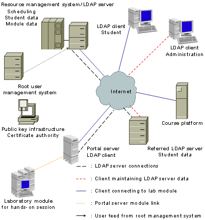
Figure 4‑1: The architecture and the possible
connections.
- Public key
infrastructure
The root certificate
authority of the single or the sub certificate authority of the hierarchical
public key infrastructure issues signed certificates, which for the installation
on the LDAP server and the portal servers. The public key root certificate
authority should integrate the root certificate in the trust lists of all
application resource users have to use. In the case that this is impossible,
users have to accept and trust the self-signed certificates of each of the
resource servers upon the first connection. Direct connections to the
certificate authority from resource servers or clients are not necessary. This
is the reason for the missing link from certificate authority to the Internet
in Figure
4‑1.
- Higher-level user
management system
The higher-level user
management system writes user accounts into the LDAP directory of the resource
management system. These updates occur automatically. This is a one-way
connection from the higher-level user management system to the resource management
system.
- LDAP client
(Administration)
An administrator connects
to the resource system to administrate the user database or the module
database. The administrator may connect to the central resource management
systems’ directory or to a referred directory if this exists.
- LDAP client (Student)
Students connect to the
resource management system if they want to book or change a booking of a
laboratory training. Students also connect to the laboratory portal servers and
to the hands-on trainings behind the portals. The third server where students
connect is the course platform.
- Laboratory portal
The laboratory portal
server connects to the LDAP server of the resource management system to
authenticate and authorize users. Only students that have booked a timeslots
for the respective laboratory module get the authorization to access the
hands-on training.
- LDAP server
If there is more than one
LDAP server present, the LDAP server of the resource management system forwards
the respective request to the referred directory.
- Course platform
If the course platform
could access LDAP directories there would be an additional connection to the
resource management system. The commercial course platform our institution
operates was not able to use such a directory and works with a proprietary
database. In the now realized form, the course platform connects to the higher-level
user management system that has identical entries as the directory in the
resource management system. There is one advantage of this drawback: all
students that get authorized to access the computer networks laboratory
resource on the course platform can access the reservation system pages provided
there and later the laboratory portal servers. This means that although all
students from the institution exist in the directory of the resource management
system, only those that also exist in the computer networks laboratory resource
on the course platform get access.
Many users visit the
computer networks laboratory resource but not all users can have the same user
privileges. Tutors must authorize students, for example to read web pages with
learning content, to access quizzes and to book modules in the reservation
system. Students should definitely not be able to access quiz solutions or
module configuration settings of the timetable. No student should be able to
delete reservations from other students. It is necessary to define user roles to
prevent the use of functions, reserved for other users. These user roles are impendent
from other user roles described in this document and only belong to the multifunctional
e-learning architecture. Each user belongs to a user role. As already mentioned
above, user roles determine different access privileges or authorization levels
of a user. In the multifunctional e-learning architecture, we have foreseen
five user roles. The first role is the global administrator. He or she has
access to the entire reservation system and to all user accounts. The second
role is the module administrator. He or she has access to the timetables
concerning the own modules and to the reservation system settings on his or her
laboratory portal server. The third user role is for resource users. They can
view the reservation system’s timetable, reserve, and free timeslots for
themselves. The fourth role is the laboratory portal user, which reads out the
LDAP directory for the actual timeslots. The fifth role is for an external
administrator, which can write into the LDAP directory of the resource
management system. This external administrator is important in the case of an
external user feed from a higher-level authentication and authorization
infrastructure, such as the institutional user management system in the case of
our institution. We list the five proposed user roles below, together with
their specific privileges:
User role 1: Global administrator
Global administrators are
the root administrators of the resource management system. They must have all
possible user privileges of the system. Global administrators cannot
automatically access the laboratory portal servers as they belong to other
administrative authorities. Global administrators are able to:
- Add,
modify, and delete user accounts in the LDAP directory.
- Set
up the reservation system with the timetables and module entries.
- Define
module timeslot lengths for each laboratory module.
- Add
or delete module timeslots for each module.
- Change
user roles from other resource users.
- Delete
module reservations of users.
- View
the real user names of the module reservations.
- Refer
the user directory to other LDAP directories.
- Access
the course platform as an administrator.
User role 2: Module administrator
Module administrators are
administrators of at least one laboratory portal server with a hands-on training.
Module administrators need to have the privileges to set up the reservation
system settings for the own module and verify existing reservations. Module administrators
are able to:
- Define
module slot lengths for the own modules.
- Add
or delete module slots for the own modules.
- Delete
users’ module reservations of the own modules.
- View
the real user names of the own module reservations.
- Access
the course platform as an administrator.
User role 3: Resource users (for example students)
Resource users are the
users that access the resource for studying. They must have enough privileges
to be able to access the web pages of the course platform and upon a successful
reservation of the laboratories together with the hands-on training. Resource
users are able to:
- View the timetables of all laboratory modules.
- Book time timeslots for all laboratory modules
in the timetable.
- Modify and delete own module reservations.
- View from other users reserved timeslots
without seeing the real names.
- Access the self-reserved modules at the
respective times.
- Access the course platform as a student.
User role 4: Laboratory portal user
The laboratory portal user
belongs to the laboratory portal servers and not to a real existing person.
Each laboratory portal uses a user name and password to query the reservation
system for the current booking state. They do not modify anything in the
reservation system. Laboratory portal users are able to:
- Query
the LDAP directory for the current module user.
User role 5: External administrator
The external administrator
is, as the laboratory portal user, not a real existing user. If a higher-level
user management system accesses the user directory for adding or deleting users
this user is used. This user has no permissions to change the reservation table
of the laboratory modules. External administrators are able to:
- Add,
modify, and delete users in the LDAP directory.
This Chapter presents the
single components of the above-described architecture in detail.
The course platform is a
combination of a resource management system with resource content servers. We
did nit develop the course platform used in the computer networks laboratory. It
is an external component. Therefore, we do not discuss the mechanisms of course
platforms in detail. As this component is a part of the architecture, we
discuss important features. A course platform that is compliant to the
autonomous multifunctional e-learning architecture accesses the LDAP server to
query user authentication and authorization data according to the LDAP
specifications. The course platform maintains an internal database for the storage
of the personal student data such as quiz results, notes, and chat sessions.
Figure 4‑2 depicts the UML activity diagram for the course
platform regarding user access and user role assigning. A person wants to login
to the course platform. He or she provides the credentials, for verification in
the resource management system’s database. Upon a successful
authentication of the person, now called user, the course platform assigns a
user role and displays the corresponding web interface. The web interfaces display
resource content or course and user configuration data originating of the
course platform’s database. Data collected on the web interfaces flow
into the course platform’s database.
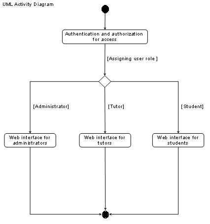
Figure 4‑2: UML activity diagram for the course platform roles.
LDAP Server and Clients
LDAP server
The LDAP directory server
is the repository for user, module, and scheduling data. The LDAP server can
have a backup LDAP server or a referred LDAP server. Students access the
reservation system on the server by web interfaces displayed in web browser
with TLS/SSL protected connections. Administrators access the database by
command line in a secure shell or by a graphical web interface such as LDAP
explorer. The course platform queries the LDAP server for user accounts and
roles. Laboratory portal users access the module data branch in the LDAP
directory to retrieve the current user for the respective module. External
administrators access the server to add, delete, and modify user data.
LDAP clients
Students access the course
platform and authenticate against the LDAP server. If there is no single
sign-on system installed, students authenticate against the LDAP database also
when they access the reservation system’s web interfaces on the LDAP server
and the portal servers for the laboratory modules. All connections to the
client’s browsers are TLS/SSL-encrypted.
Administrators access the
respective directories where they possess the administrative responsibility for
the user data. The module administrators can define the settings of the
reservation system: starting time of the first lot, the slot length, and the
period where he or she wants to add lots to the timetable of the reservation
system.
Interactions with the LDAP directory
The LDAP server operates the
database of the LDAP directory it is thus called directory instead of database.
If there is a higher-level user management system, a process must register user
accounts from this database in the resource’s LDAP server directory. If
there is a referring database, it must also conform to the LDAP standards and
the respective data exchange policies. Persons accessing the course platform,
content providing servers, the reservation system, and the laboratory portal
authenticate against the LDAP server’s directory and are authorized with
the information stored in the directory. Upon a successful authentication and authorization,
these persons are allowed to access the course platform, the content providing
servers, the reservation system, or the laboratory portal, respectively.
Administrators can add, modify, and delete user accounts, and module data in
the resource management system’s database. Resource content providing
servers, the course platform, and the laboratory portals can read out user
data, meanwhile the laboratory portal also reads out the module data, i.e. the
current user and the timeslot duration. The reservation system reads out module
and user data from the resource management system’s database to display
the timetables with the module reservations. It writes into the resource
management system’s database to set timeslots and the current users of
the modules.
This section discusses the
concept behind the laboratory portals used in the multifunctional e-learning
architecture. We start with a presentation of the requirements to such a
portal:
- Interface to the
laboratory devices
The interfaces to the
laboratory devices are responsible for the communication of the portal with the
connected devices of the respective resource module. The portal manages and
monitors the functionality of the connected devices. It is possible to use
Ethernet, Serial and USB connections or any other connection, which allows
establishing a connection between the portal server and the laboratory devices.
- Interface to the
students
The laboratory portal is
the entry point for the students accessing the laboratory devices. The
laboratory portal hosts a web server, which provides the necessary web sites of
the laboratory module. The portal is also the checkpoint for the user
credentials.
- Interface to the user
database
The interface to the user
database is necessary for the user authentication and authorization. We recommend
querying only the central user directory, and not referred directories. A
possible technology to query the LDAP directory is the Pluggable Authentication
Module (PAM) [SS95].
- Interface to the
resource course platform
This interface to the
course platform system is rather an interface from the course platform to the
laboratory portal. The course platform leads students through the hands-on training
and directs them to the portal server whenever actions on the laboratory
devices are required. It is also possible to feed back user data to the course
platform, for example about exercise results.
- Interface to the
reservation system
The interface to the
reservation system is of importance if the resources of the laboratory module
are limited. This is the case if real devices are used and not emulations and
especially simulations. Through this interface, the laboratory portal receives
authorization data for the students.
- Interface to the
billing system
The interface to the
billing system sends back accounting data to the resource management system.
- Firewall
The laboratory portal is something
like a broker with many connections in from the Internet and Intranet. The
laboratory portal acts as a firewall due to the ability to decide which data,
originating from the exterior interface and traveling to interior interface, can
pass.
The laboratory portal
server is the unit, which connects the different laboratory modules to the
resource management system. The portal server separates the Internet from the
internal laboratory network and acts as a firewall. Students access the portal
server by web browsers with SSL connections and by secure shell applets for web
browsers. The portal server forwards those sessions to the respective
laboratory devices. The portal server authenticates users against the LDAP
server if there is no single sign-on system installed and authorizes users by
querying the reservation system. Links to the LDAP server are encrypted using
IP security or Stunnel technology.
Each laboratory portal
server queries the module tree in the LDAP directory of the reservation system
with a read out user to query the current user of the respective module. In the
case that no reservation for a slot exists, the current module user is set to
dummy as each query to the LDAP database has to return a valid result. If the
module slot reservation exists, the current module user name is returned to the
laboratory portal server. The student can thus enter to the hands-on training
by either authenticate again to the LDAP directory or through single sign-on
mechanisms.
Figure 4‑3 depicts the UML activity diagram and Figure 4‑4 the UML sequence diagram of a person accessing a
laboratory portal. In a first step, the person has to authenticate against the
resource management system’s database. Upon a successful authentication,
the user accesses the laboratory portal’s entry page. The laboratory
portal now checks if a reservation for the user and module is available. If
not, the portal logs out the user. If yes, the user accesses the web interface
for the device selection of the hands-on training. During the hands-on training,
the laboratory portal queries the timetable at regular intervals or safes the
slot lengths at the beginning of the session and logs out the user when the session
ends.
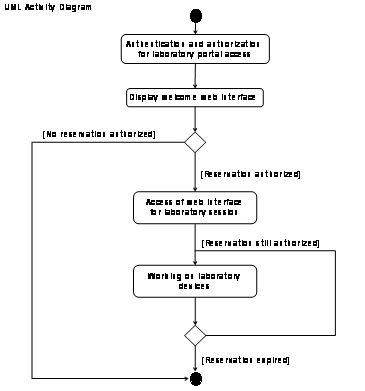
Figure 4‑3: UML activity diagram of a person accessing
a laboratory training.
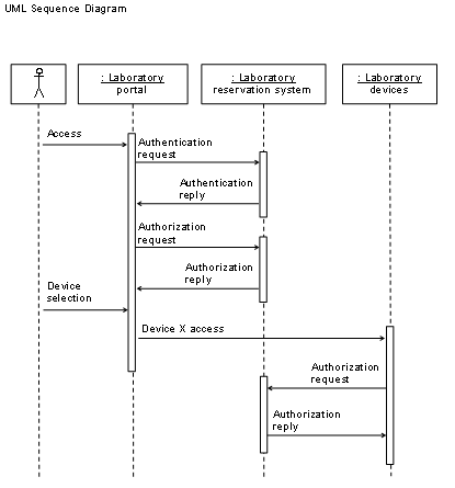
Figure 4‑4: UML
sequence diagram of a person accessing a laboratory training.
Laboratory Devices
The laboratory devices can
consist of everything pluggable to the laboratory portal server. Via Ethernet
connected laboratory devices belong to the internal network and are isolated
from the Internet by the portal server. The same is valid for all other
connection types between the portal server and laboratory devices: it is necessary
to isolate laboratory devices from the Internet for security purposes. The
portal server forwards incoming user sessions for example through Telnet or Minicom
to the laboratory devices.
The laboratory portal verifies
already authenticated and authorized user for a valid reservation against the
reservation system’s database regularly. If the user has a reservation,
he or she gets to the hands-on training web interface and has the possibility
to choose the laboratory devices. The laboratory portal displays or re-issues this
web interface only when a valid reservation exists. The device logins in this
dynamically created web interface consist of links enhanced with the device
name and a temporary password originating from the laboratory portal’s
database. If the user logs in to a device, he or she can work until the
reservation is no longer available. Then, the portal terminates all user
processes. It kills the user session and prevents a re-login, as the temporary
passwords are no longer valid. Only the next user who accesses the hands-on trainings
gets new passwords, embedded in the laboratory screen.
User Interactions with the Reservation System and the
Laboratory Portal
In this section, we present
three out of many possible UML use case diagrams for users of the computer
networks laboratory resource. The first three diagrams show the interactions of
a student, a module administrator, and a global administrator with the resource
management system, respectively. The forth diagram depicts a UML sequence
diagram for students’ booking interactions.
In the first diagram shown
in Figure
4‑5, a student accesses the resource management system
for the first time. He or she has to register with the resource management
system, in our case on the course platform and wait for the approval or
disapproval of the administrator. If the student gets the approval, the administrator
authorizes him or her to access the course platform and all web pages
accessible for students. The student now studies the resource content and books
timeslots of laboratory modules. The resource management system shows the
respective timetables with the free, booked, or self-booked timeslots. After a
successful module reservation, he or she can access the respective laboratory
module and attend the hands-on training.
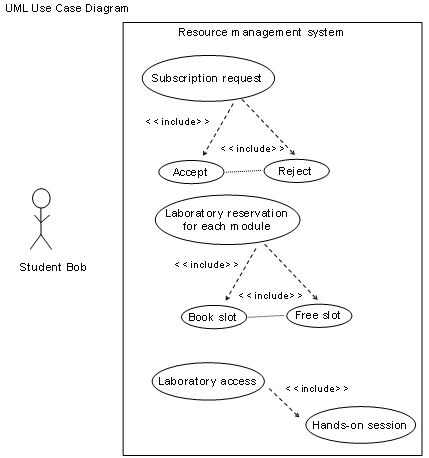
Figure 4‑5: UML use case diagram for student access.
Figure 4‑6 shows the UML use case diagram for a global resource
administrator, which manages user and module settings on the resource
management system. The global administrator adds, deletes, or modifies user
accounts. Subsequently, the resource management system updates the database
with the changes (for example, delete module reservations of deleted users).
The global administrator is also able to change the user roles of users in the
directory. The global administrator specifies the global settings for the
module reservation system (manages the booking table) i.e. he or she adds new
modules, deletes, or modifies existing modules. The global administrator can
define slot lengths for all modules and add timeslots to the timetable.
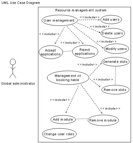
Figure 4‑6: UML use case diagram for resource
management.
In the UML use case diagram
shown in Figure
4‑7, a module administrator responsible for one or more
modules, applies for a new module identity (mid) number by the global resource
administrator. The global administrator adds, modifies, and deletes the module
in the resource management system. The module administrator can now define the
module settings consisting of the module slot length, slot starting time and
slot expiration date and the resource management system displays the timetable.
The module administrator now configures his or her laboratory portal server for
the reservation system access, and the laboratory portal server queries the
resource management system for bookings at regular intervals.
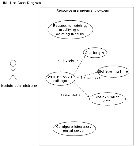
Figure 4‑7: UML use case diagram for module
management.
Figure 4‑8 shows the possible students’ interactions on
the web interface for module reservations of the computer networks laboratory
in a UML sequence diagram. The diagram integrates three components, the
students accessing a web interface, the scheduling script, and the LDAP server
such as the laboratory portal. The scheduling script is the program code
composing the dynamic pages for the web interfaces and setting the reservation
data in the LDAP server. Students can query the timetable for each of the
existing modules. They add, delete, or modify reservations for each module via
the web interface. The booking interactions on the web interface trigger the
scheduling script, which updates the LDAP directory on the LDAP server.
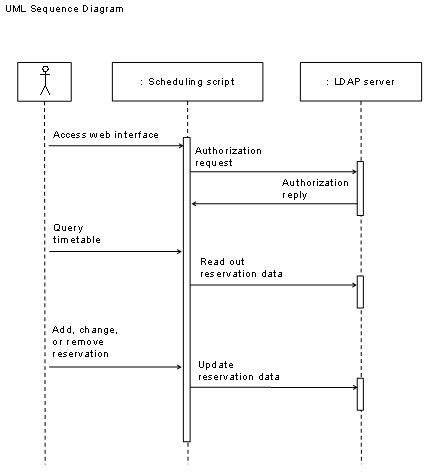
Figure 4‑8: UML sequence diagram for students’
booking interactions.
Figure 4‑9 show the UML sequence diagram for a student
accessing a laboratory portal server. The student accesses the web interface on
the laboratory portal and needs to authenticate against the LDAP server. The
LDAP client on the laboratory portal queries the LDAP server at regular time
intervals for the current module users for its module. If the current module
user changes, the laboratory portal terminates all student processes and
changes the passwords for the laboratory devices in the dynamically generated
web interface.
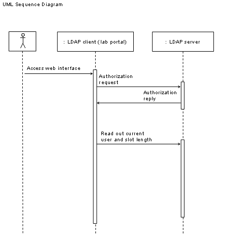
Figure 4‑9: UML sequence diagram for students’ lab portal interactions.
4.3.5 Security Issues
We recommend to encrypt all
connections in this architecture, except those behind the laboratory portal
servers in the laboratory environment. The certificate authority is used to
issue keys for IP security connections, for SSH connections, and for SSL connections.
Students and tutors connect with SSL or with secure shell through the portal to
the laboratory equipment. There is no technical obstacle against using Telnet
or clear text HTTP connections for connections to the portal servers but as
students transmit passwords and personal data it seems already old-fashioned
not using encrypted connections. Servers use either IP security connections or
Stunnels for their data exchange.
The implementation Chapter comprises four Chapters, discussing the implementation of the course platform, of the resource management system, and of one laboratory module.
The prototypically implemented
computer networks laboratory uses a commercial course platform. This commercial
course platform is not able to read out LDAP directories. As a consequence, the
computer networks laboratory’s LDAP directory is synchronized once a day
with the course platform’s directory through a script, which reads out
user data in the universities LDAP directory and writes the user data into the course
platform’s database and the resource management system’s LDAP
directory.
Figure 4‑10 depicts the implemented architecture and highlights
the differences realized compared to the original architecture. The architecture
now comprises a higher-level user management system. As described above, this
database registers users in the course system’s database as well as in
the proprietary database used in the course platform. This procedure guarantees
that all the databases have always the same entries. A negative aspect of this
change to the original architecture is that administrators must manually assign
user roles for the courses on the course platform.
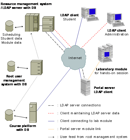
Figure 4‑10: Implemented architecture with course platform.
4.4.2 Resource Management System
We implemented the resource
management system with the OpenLDAP [Open] distribution, an open source LDAP
implementation. The LDAP server runs on a Debian Linux operating system. The
programming language for the scheduling scripts and for the web interfaces is
PHP for the same reasons as with the resource management portal: PHP is easy to
implement, adapt and can be integrated in HTML code as well as it allows the
creation of dynamic web pages on the server. PHP supports the LDAP protocol
with and API.
Student and module data are
stored on the LDAP directory server, with a scheduling script as an interface
between the web interfaces and the data sets. The scheduling script has the
ability to read and write into the LDAP data sets and thereby set the
reservation states for the modules.
Student data sets can
contain personal information such as matriculation number, institute, Email,
and must contain user name and password. They are stored in the organizational
branch UniversitätBern in the sub branch Users. The distinguished name looks
like Figure
4‑11 depicts:
dn:
cn=NameSurname,uid=UserName,ou=Users,o=UniversitätBern,c=CH
Figure 4‑11: DN for student data.
The current user script
copies the current user of a module from the timetable to the respective module
data set. The laboratory portal servers read out their respective data sets. Each
module’s reservation data is stored separately in the organizational
branch of the NetworksLaboratory, sub branch Modules in the sub branch mid (mid
stands for module identity). The distinguished name looks like Figure 4‑12 shows:
dn:
mid=1,ou=Modules,o=NetworksLaboratory,c=CH
with
the data:
objectClass: module
objectClass: alias
mid: 20
firstslot: 0000
slotlen: 1
numslots: 24
aliasedObjectName:
uid=dummy,ou=users,o=NetworksLaboratory,c=CH
Figure 4‑12: DN for module data.
The timetable is located in
the organizational branch of the NetworksLaboratory, sub branch Timetable in
the sub branch mid. The distinguished name looks like Figure 4‑13 shows:
dn: slot=19680518 2130
0400,mid=1,ou=Timetable,o=NetworksLaboratory,c=CH
with
the data:
objectClass: timetable
objectClass: alias
slot: 19680518 2130
expires: 20982330
aliasedObjectName:
uid=dummy,ou=users,o=NetworksLaboratory,c=CH
Figure 4‑13: DN for timetable data.
Staff data is stored in the
in the organizational branch NetworksLaboratory, sub branch Staff. The
distinguished name looks like Figure
4‑14 shows:
dn:
cn=NameSurname,uid=UserName,ou=Staff,o=UniversitätBern,c=CH
Figure 4‑14: DN for staff data.
Figure 4‑15 depicts the implemented LDAP directory structure. The
Figure shows the four levels of the directory tree. The top level is the
country level with CH for
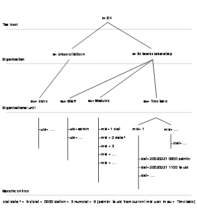
Figure 4‑15: LDAP directory structure.
Figure 4‑16 shows the web interface for laboratory
module reservations. This web interface and the PHP script beyond is used to
write pointers to the user names from the ou=Timetable branch to the ou=Users
branch in the LDAP structure depicted in Figure
4‑15. Students select the respective module on the top of
the page and then see a timetable showing the reservation state of the current
week. It is possible to browse forwards and backwards and to see the past
reservations as well as to make reservations in the future. A green circle
represents a free timeslot, a red cross an already booked timeslot. The blue
checkmark stands for a self-booked timeslot. The timeslot length varies from module
to module, so do the hands-on training starting times. Both can be configured
by the respective module administrators, who get these configuration settings
displayed if their uid is found in the branch ou=Staff.
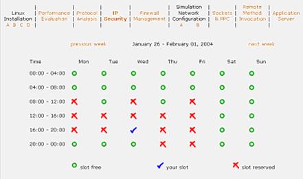
Figure 4‑16: Module reservation web interface.
Each minute, a cron job is started for checking the
reservations in the ou=Timetable branch depicted in Figure 4‑15. The PHP script afterwards writes pointers for the
current reservations from the ou=Users branch into the ou=Modules branch. Doing
so, all the laboratory portals are able to read out their respective current
user in the ou=Modules branch. This is the only and single point, where the
laboratory portals’ LDAP clients retrieve module state information from
the LDAP directory database. The PHP script behind the web interface depicted
in Figure
4‑16 reads out the data from the ou=Timetable branch. If
the pointers to the ou=Users branch lead to the same uid as the logged in user
possesses, the blue checkmark appears. If there is a pointer to a different
uid, the red cross appears. If there is a pointer to the uid=nouser, a green
circle appears and the logged in user can book the slot. The uid=nouser is a
placeholder for not booked timeslots in ou=Timetable branches.
The laboratory portals serve the PHP entrance web interface for
the computer networks laboratories. The PHP script on the laboratory portal
displays the login screen first and then authenticates the user against the
branch ou=Users on the LDAP server. The authenticated user’s uid is used
to make an authorization query to the ou=Modules branch and the respective mid.
If the PHP script encounters the same uid, as the logged in user possesses, the
web interface displays the hands-on training page, started by the reservation
script. The web interface can also display reservation state messages if the
query was not successful. In case of errors, the page provides further
information about the type of error, such as non-existent users in the LDAP
database or non-existing reservations for the respective module.
4.4.3 Laboratory Module Implementation
Transition from Traditional Exercises to E-Learning with the Example of the Module IP Security
In one module of the
traditional computer networks laboratory, students configure commercial routers
and use hosts with pre-installed network-testing tools. The IP Security
module’s hands-on training mainly consists of two parts:
1) In the first part, students
learn to configure two routers in order to set up a secured virtual private
network tunnel between the routers.
2) In the second part, the students
have to perform measuring tasks. They analyze traffic on the virtual private
network link, using a bandwidth measurement (network capacity) tool, called
NetPipe [TX02]. The must analyze encrypted and clear text traffic with TCPdump
to verify the traffic condition.
The module IP Security was
the first computer networks laboratory module implemented in the e-learning
resource. The starting point for this e-learning module was our traditional
in-house laboratory module IP Security. Figure
4‑17 shows the transition process to the e-learning
version. The isolated laboratory network, depicted on the left side of the
Figure was connected to a laboratory portal server and additional connections
were made with the routers over serial links. That way, the portal server
manages the routers and the hosts. The serial links to the routers serve to
forward the secure shell sessions from students accessing the portal sever via
a transparent program to the routers and provide the feeling of accessing the
routers directly with the secure shell. Additionally, the portal server remotely
controls the routers during the reset phase.
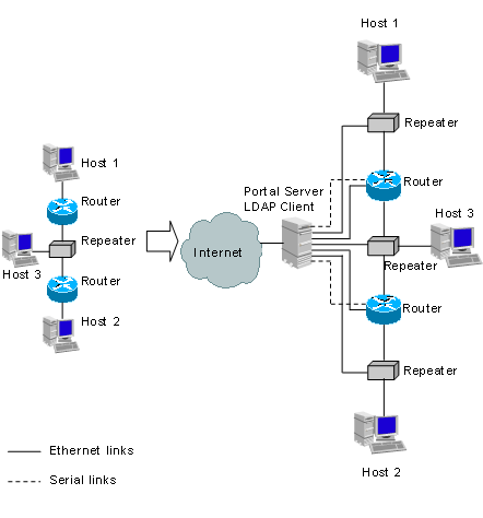
Figure 4‑17: From traditional to e-learning.
Module Implementation
Figure 4‑18 gives an overview of the IP Security module
implementation [ZSB03 and Zs03]. The portal server is connected to the Internet
and to the laboratory devices by Ethernet links and acts as a gateway between
them. There are three network interfaces to the laboratory devices, i.e. one to
each repeater. The repeaters are between host 1 and router 1, host 2 and router
2, and between the routers and host 3. In this way, it is possible to connect
to all the network interface cards of the laboratory devices by Ethernet links.
However, for managing the routers it is not enough to have Ethernet links to
the routers because students can easily shut down them and the routers become
unreachable. For that reason, the portal server has serial links to each of the
routers’ console ports. These serial links allow permanent configuration
access to the routers by the portal server. The Figure also shows the alternating
current power links. The relay card, managed by the portal server, can
interrupt the power of the two connected routers. We describe the details of
this process below.
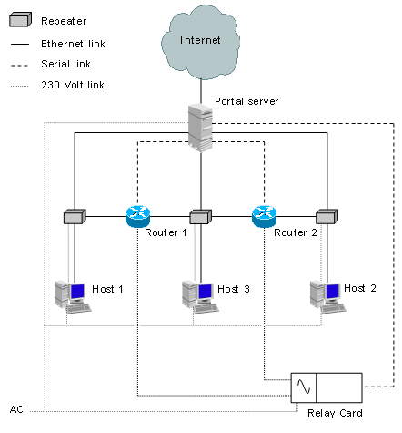
Figure 4‑18: Portal server and laboratory devices.
We created a dedicated user
account for each laboratory device (router 1, router 2, host 1, host 2, and
host 3) on the portal server. When the laboratory user logs into the portal
server, the portal server automatically forwards this user to the corresponding
laboratory device and he or she can start with the configuration. This
mechanism was realized for the three hosts by changing the users’ login
scripts that automatically forwards them to the corresponding host via the
standard “rlogin” command and logs in. “rlogin” does
not represent a security risk, because these logins are transmitted over an
internal subnet, which is separated from the Internet through the portal
server.
We could not use the same
mechanism for the router users as for the host users. A login to the routers
via the Ethernet link is not possible as long as the routers’ links are
not set up (for example after a reset) or are down due to a misconfiguration
(for example by the student). To prevent management problems of the routers,
the router users’ login scripts start the terminal program directly after
the login. The terminal program is installed on the portal server. The settings
of the terminal program are pre-configured to connect the user to the
router’s console port via the serial link. With this mechanism, it is
always possible to access the routers, independent of their Ethernet link state.
When the router user quits the terminal program, he or she is automatically
logged off from the portal server.
The portal server runs an
Apache web server with the modules PHP, Perl, and SSL loaded. We developed PHP
scripts, which create dynamic HTML pages. These pages represent the main
interfaces between the students and the network hardware and allow them to communicate
with the laboratory hardware.
Configuring routers is not
a simple task and students without experience can get lost during the
configuration. It is also possible to configure the routers in a way that only
a reset can help. Students must have administrator access to the routers to
setup Ethernet links and to configure the routing tables and protocols. A person
with administrator access to the routers can also set a new administrator password
and block the routers for others. To prevent this, we implemented a hard reset
mechanism for the two commercial routers used in the IP Security module. By
means of this mechanism, routers can be reset to a minimal configured state and
administrator passwords deleted. The mechanism uses a documented password
recovery procedure, which normally is only applicable with a directly to the
router connected console device.
To overcome this
limitation, we first power-cycle (power off and power on) the routers and then
configure the routers over the console port. In detail, we send a break signal
to the routers at an exactly defined moment after power-cycle over the console
port. This brings the router into the bootstrap program where it is possible to
load another system image (called Internetwork Operating System (IOS) by Cisco)
into the router. In this special maintenance mode, it is possible to configure
the router such that it “forgets” its current configuration,
especially a set administrator password. We achieve this by changing a
configuration register, which holds the address from where the routers initially
boot the IOS. We save this current stored address for later use on the portal
server. After setting the register to an invalid value and rebooting the
router, we set the configuration to a minimal state and delete the
administrator password. Then we login again and set the configurations-register
value back to the old address, saved before. After a reboot, the router is
ready to use again.
We inserted a relays card between
the routers and the electrical power socket to automate the power cycling. We connected
the relays card to the portal server’s serial port. The relay card consists
of a small microprocessor, which controls the relays’ state. The
communication between the portal server and the relays cards’
microprocessor uses a proprietary protocol with four-byte frames commands. For
each command frame sent from the portal server to the micro-controller, the portal
sends back an answer frame.
We developed a Perl-based
driver library of the frame-based protocol. Because the library communicates
with the relays-card’s microcontroller over the serial line, the existing
Perl module Device:SerialPort was included. This Perl module provides functions
for sending and receiving data over a serial-line interface and is the basis
for our developed driver library. Furthermore, the module Device:SerialPort
offers a function to send a break-signal over a serial-line, which is necessary
to put the booting router into the bootstrap program.
By the use of the developed
library functions, it is possible to control the relays card and to set and get
the relays’ state. Therefore, it is possible to power on and power off
each of the routers by switching the corresponding relays of the relays card on
and off. As described above, for fulfilling the password recovery, we must send
a break signal to the router and change a configuration register. We achieved this
by implementing a Perl script, which uses the relays card’s library. This
script brings the router into the bootstrap program after the power cycle and
sends the confreg-command over the serial line as if an administrator would do
by connecting a laptop to the router. Then the script sends the reboot command
to the router and waits. The reboot clears the before set router passwords. Now
we have to write back the before saved configuration register’s value. We
do this with the Perl script and then reboot the router again. The whole reset
procedure lasts about five minutes.
User/Laboratory Portal Interactions
Figure 4‑19 shows the laboratory page, the individual page of
each hands-on training, displayed after the login. In the case of the IP
Security module, the laboratory portal server displays the laboratory bed with
additional information such as IP numbers and available interfaces. Students
click on the devices to open shell connections.
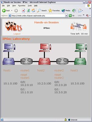
Figure 4‑19: IP Security hands-on training.
Figure 4‑20 shows the interactions between the students, the
resource management system, i.e. the reservation system and the laboratory
portal. We explain the single steps.
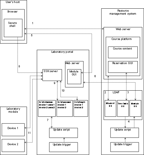
Figure 4‑20: User interactions with management system
and portal.
1) The user accesses the login
page on the web server of the course platform and logs in with his or her
credentials.
2) The web server verifies the
credential with the student database in the LDAP directory.
3) Upon a successful login,
the user accesses the web interface of the reservation system. He or she can
now choose the available modules and book, modify or delete timeslots for the
laboratory modules. The reservations are stored in the timetable database in
the LDAP directory.
4) The update trigger (a CRON
job) on the host of the resource management system runs the update script (the
above-mentioned scheduling script) at regular intervals (recommended once a
minute). The update script reads out the timetable database and writes the user
data of the current module users into the module database.
5) The user has now the
possibility to access directly the laboratory portal’s web server if he
or she knows the URL or to access it through the course platform. He or she
gets to the laboratory portal server’s graphical user interface. If there
is no single sign-on system installed, the user has to provide his or her
credentials again.
6) The laboratory
portal’s web server accesses the module database of the LDAP directory to
verify if the user has booked the timeslot. The laboratory server also receives
the start and end times of the timeslot. The web server now generates a session
cookie, which is valid up to the end of the timeslot and allows the user to
re-open the laboratory configuration page without a repeated login. Then the
user accesses the laboratory web pages with dynamic URL for the secure shell
applets. The user connects with the secure shell applets to the laboratory
equipment. The URL for these applets also contain the user name (i.e. the
device name) and on the fly generated session passwords.
7) In the meantime, the update
script has written the session passwords into the file /etc/shadow.
8) Upon a click on a
laboratory device on the web page with the laboratory bed, the user’s
browser loads the secure shell applet and connects to the laboratory portal
server.
9) The secure shell applet
uses the user name and the session password that have been stored in the
dynamic URL and that is stored in the file /etc/shadow.
10) Upon a successful login,
the portal server starts the communication to the laboratory device and logs
the user directly to that connection (i.e. instead of getting to a console
(e.g. bash) the user gets to the communication linking program (e.g. Minicom).
11) The user is now on the
respective laboratory device and can use it up to the end of the timeslots.
4.5 Discussion and Conclusions
With the presented multifunctional e-learning architecture, it
is possible to connect multiple geographically distributed e-learning resources
together and thus forming an e-learning grid environment. Partners of this grid
profit from the shared knowledge, labor, and expenses. The knowledge remains
where the content producers reside. We specially designed the grid is specially
for connecting real devices for hands-on trainings in e-learning laboratories.
This remains an expensive procedure but is simplified with well-defined
interfaces and software applications offered by this architecture and its implementations.
Simulations or emulations would require significantly more time and money for
the implementation with the same functionalities as real devices provide. It is
possible to update easily the firmware of real devices and without changing software
code, whereas simulations and emulations require a further development for each
change. Another advantage of real devices lies in the possibility to exchange
those devices immediately. The inclusion of real devices in e-learning and not
only simulations and emulations allows educating with the same means as in
traditional laboratories.
The central resource management system, built on the
lightweight directory access protocol, integrates the necessary reservation
system together with the students’ and tutors’ account management
system. This is necessary for opening hands-on trainings e-learning
laboratories to the Internet. The architecture enables operators of traditional
computer networks laboratories or of laboratories with real devices, which are
pluggable to a computer, to connect the devices to laboratory portals. The
laboratory portals are brokers between the students, the course management
system, and the laboratory devices. The laboratory portals also fulfill
security functions while acting as firewalls between the Internet and the
Intranet with the laboratory devices. The architecture thus integrates user and
resource management as well as security features. LDAP proofed to be a robust
choice related to authentication and authorization issues. The realization of
the laboratory reservation system in LDAP is unique in the world and works fine
although future feature extensions are hardly realizable as the LDAP directory
is not a relational database. We could not fully profit from LDAP, as it was
not possible to refer the course management system’s directory to the
directories of the partner universities involved in the computer networks
laboratory. The LDAP referring procedure is not realizable because the directory
access policies do not scale if established across institutional borders.
Among other learning units, the laboratory of the module IP
Security was connected to the course system. From 2001 to 2004, about 400
students used the module for their education. The remote control of the routers
and hosts belonging to the laboratory works fine and few problems have arisen.
Blackouts with subsequent file system damages caused major problems. Therefore,
we installed uninterruptible power supplies. Minor problems aroused by hardware
failures such as CPU fans stopping cooling or defect network cable plugs. As a
result, we regularly check the hardware for defects and changed the physical
laboratory setup.
All the succeeded implementations use standard low-cost
computer equipment and self-developed open source code to facilitate
dissemination in the educational environment in rich and poor countries and are
as well platform and operating system independent. The design decisions raised
interest in many demonstrations. In our realization of the e-learning
laboratory, we use a commercial course platform operated by the university,
freeing us from update and maintenance load. This design changes profess the
flexibility of our architecture.
Many additional developments and not yet made implementations
could be realized in future. We propose to subordinate the architecture to a
higher-level user management system to decrease administrational overhead. We
propose to do his with the integration of a broker between the architecture and
higher-level user management system.
The reservation system, a part of the course management system
in the distributed architecture, could be enhanced by user profiles, which
identify the students. Such profiles could for example mark a student as a full
or part-time student. The profiles could serve to reserve blocks of timeslots,
for example evenings for part-time students or give students a time account per
laboratory module.
Another enhancement concerns teamwork, which is absent up to
now. Students should have the possibility to form groups. Student profiles
could be used to allow students to find workmates.
The current version of the reservation system is not able to
show timetables for modules with multiple laboratory instances. Instead, each
module instance occupies a single timetable. Usability could be improved significantly
by developing multi-instance capable timetables.
The reservation system should adapt times displayed to the user’s
time zone and also be localized using the I18N scheme. Such functionality could
be implemented in the client’s graphical user interface.
The course management system could be enhanced with charging
and accounting functionalities. Information such as such as who reserved which
slot and how long the respective user remained in the slot performing the
hands-on training should be available for tutors and administrators.
The prototypically implemented laboratory module IP Security
could be enhanced in various ways. The hands-on scenarios of this module could
be enhanced by providing the possibility to select among different firmware
versions of the routers. Different versions of the firmware support different
features, such as firewall or multi protocol label switching functions. Support
for several firmware versions could be achieved by setting up a Trivial File
Transfer Protocol-server (TFTP) on the laboratory portal server and storing the
required firmware files.
The Ethernet network settings of the Linux hosts in the IP
Security module are pre-configured, because students only perform measuring
tasks. A possible extension of the module scenario could be that students have
to set up the network settings of the hosts from the scratch. In this case,
students must have root access. Because root access to the hosts might result
in unstable or corrupt systems, a possibility to reset the hosts to a known
state is necessary. Such a configuration reset could be achieved by power
cycling the hosts in the same manner as discussed for the routers. The hosts
would have to boot from the built-in CD ROM drive or the disk drive. This
bootable medium should contain a small Linux system, which would get an IP
address from the laboratory portal server via dynamic host configuration
protocol (DHCP) and then fetch an image file from a TFTP server. The image
would be extracted on the host and the pre-configured Linux system stored in
the image would be ready again.
5
Extended
Multifunctional
E-Learning Architecture
This Chapter presents and discusses the reasons and the
required changes for the transformation of the multifunctional e-learning
architecture to the extended multifunctional e-learning architecture. The
motivation for the extension of the multifunctional e-learning architecture
originates in the easier user administration achieved with the sub ordination
of the architecture to a higher-level user management system and the increase
of the potential audience for e-learning courses. Another achieved advantage is
the state-of-the-art user authentication method provided by the higher-level
user management system and used in the entire architecture. We define the
extended multifunctional e-learning architecture as architecture, where the
authentication process, integrated in the multifunctional e-learning architecture
was removed and handed over to a third party user management system. Such a third
party user management system, in the form of an authentication and
authorization infrastructure is Shibboleth. The extended multifunctional
e-learning architecture now integrates the authentication and user registration
functionalities from Shibboleth. It links the multifunctional e-learning
architecture together with the resource management portal architecture.
Chapter 5.2 discusses the transformation approach for the
architecture and Chapter 5.3 describes the architectural elements. We also show
the elements originating from the multifunctional architecture and the newly
designed elements.
The extended multifunctional e-learning architecture is a
special case of the multifunctional e-learning architecture. In other words, it
is an extended but to a specific environment adapted case. The reminder of this
Chapter discusses the concepts of the transformation as well as the
architectural background.
The architectural specifications remain the same as described
in Chapter 4.3 with these two exceptions:
- All architectural
components with direct user access must be Shibboleth-enabled
(shibbolized). This concerns the reservation system and the laboratory
portals.
- Shibboleth home
organizations’ authentication functionalities with single sign-on
login functionality replace the LDAP-based user authentication
functionality.
Table
5‑1 compares the two architectures. Features provided are
marked as X, features provided under certain conditions as (X). In both
architectures, it is possible to add local user accounts manually to the
resource management system or to let higher-level user management systems write
directly into the database. In the original architecture together with a
commercial course platform, it is possible to add users to the course platform
only by the higher-level user management system because the course platform
reads out a proprietary database, fed by the higher-level user management
system and not the LDAP-based resource management system. In the extended
architecture, we still integrate the same course platform, but this time the
users originate from the authentication and authorization infrastructure. The
resource management portal thus adds the users to the resource management
system as well as to course platform. The higher-level user management provided
authentication with the respective home organizations replaces the LDAP authentication
of the original architecture. This means that each accessible component must be
Shibboleth-enabled: the resource management system for the reservations, the
laboratory portals, and the resource management portal. As all Shibboleth home
organizations implement single sign-on solutions in combination with the origin
site installation, the extended multifunctional e-learning architecture becomes
single sign-on-enabled. The authorization within the extended architecture
still succeeds with LDAP in form of laboratory portal servers querying the
reservation system for valid reservations. The resource management portal now
performs the course access authorization. The base for this authorization build
he user information attributes released by the users’ home organizations
as well as the additional user information collected on the portal.
|
Multifunctional e-learning architecture |
||
|
Feature |
Original |
Extended |
|
Local
accounts in the resource management system |
X |
X |
|
User
registration through higher-level user management system |
X |
X |
|
Authentication
with LDAP |
X |
|
|
Authentication
with Shibboleth |
|
X |
|
Authorization
with LDAP |
X |
X |
|
Single
sign-on |
(X) |
(X) |
|
Laboratory
portals query for current user |
X |
X |
|
LDAP-based
resource management system |
X |
X |
Table 5‑1: Comparison of original and extended
architecture.
Figure
5‑1 compares the user login processes in the original and
the extended architecture. We explain both access procedures below:
- In the original
architecture, the higher-level user management system adds the user to the
resource management system and to the course platform prior to the first
user access. The user then accesses the course platform and authenticates
against the built-in proprietary course platform database. The user
accesses the reservation system and the laboratory portals out of the
course platform or if the URL are known directly by LDAP-authentication
against the resource management system. The laboratory portal queries the
reservation system for the current user, in this case the user name @
organization. The reservation system authorizes the user to access the
laboratory session or not. The reservation system allows adding, changing
and deleting module reservations.
- In the extended
architecture, the resource management portal adds the user to the
reservation system and to the course platform. In a first step, the user
has to access the resource management portal and pass the Shibboleth
authentication process, performed by his or her home organization. After
subscribing to the resource and the clearing by the portal administrator,
the user can access the resource. The resource management portal adds the
user to the resource management system’s database and at the first
access to the course platform to course platform’s database. Between
the course platform in use and the resource management portal exists a
shared secret, which is used to HTTP-redirect and automatically login the
user to the course platform out of the resource management portal. The
user must always login to the course platform via the resource management
portal. The user accesses the reservation system and the laboratory
portals out of the course platform or if the URL are known directly by
Shibboleth authentication with the respective home organization. The
laboratory portal queries the reservation system for the current user, in
this case the unique authentication and authorization infrastructure identity
@ home organization and the reservation system authorizes the user to
access the laboratory session or not. The reservation system allows adding,
changing and deleting module reservations.
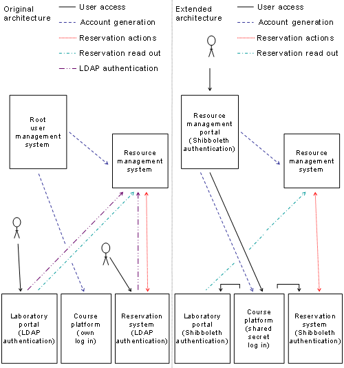
Figure 5‑1: Comparison of user login.
The architectural requirements discussed in Chapter 4.2 did not change and thus a sub Chapter with new
architectural requirements is obsolete.
5.3 Architectural Specifications
The architectural specifications discussed in Chapter 4.3 have only slightly changed. Particularly the overview
remains identical for the extended multifunctional e-learning architecture. We
thus start with the discussion of the overall architecture and the integrated
new components. We then discuss the user roles of this architecture before we
present the single components of the extended architecture in detail.
Figure
5‑2 shows the extended architecture with the components
and their possible connections between each other. Connections between servers
use Stunnel technology whereas connections between servers and end users
TLS/SSL. We discuss the possible connections between the components in detail
below.
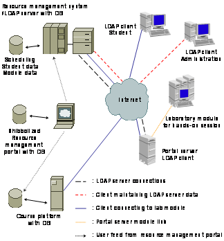
Figure 5‑2: Dependent multifunctional e-learning
architecture.
The components and their functionality:
- Public key infrastructure
The higher-level certificate authority of the
single or the sub certificate authority of the hierarchical public key
infrastructure issues signed certificates, installed on the Shibboleth-enabled
servers, such as the resource management portal, the LDAP server, and the
portal servers. Everything else remains as discussed in Chapter 4. We recommend using the same public key
infrastructure as the authentication and authorization infrastructure uses,
also for server to server and server to client connections.
- Higher-level user management system
The higher-level user management system writes user
accounts into the LDAP directory of the resource management system. These
updates occur automatically. This is a one-way connection from the higher-level
user management system to the resource management system. The higher-level user
management system in the extended architecture is the resource management
portal. It is possible to use more than one higher-level user management system
at once, i.e. more than one resource management portal.
- Resource management portal
The resource management portal is the entry point
for students accessing the computer networks laboratory connected to the
extended multifunctional e-learning architecture. All accesses to the course
platform work only over the resource management portal, laboratory portals and
the reservation system could theoretically be accessed directly if the URL are
known.
- Client (Student)
The students now firstly access the resource
management portal instead of the course platform. Students are no longer LDAP
clients as in Chapter 4 but are authenticated accordingly to the
authentication system used by their respective home organization.
- LDAP client (Administration)
This remains as discussed in Chapter 4.
- Laboratory portal
The laboratory portal server connects to the LDAP
server of the resource management system to authorize users by reading out the
current user of the hosted laboratory. Only students who have booked a
timeslots for the respective laboratory module get the authorization to access
the hands-on training.
- LDAP server
The LDAP server of the resource management system
now stores the users as unique AAI identity @ home organization in the
database, used for the laboratory module reservations. Everything else remains
as discussed in Chapter 4.
- Course platform
The course platform remains as discussed in Chapter
4, especially the fact that the course platform should
be able to read out the LDAP server. As this is still not the case, the
resource management portal was connected to the course platform and
automatically opens and maintains user accounts on the course platform.
It was necessary to redefine the user roles of Chapter 4 for the extended multifunctional e-learning
architecture. User roles help to prevent the use of functions, reserved for
other users. These specific user roles are independent of other user roles
described in this document and only belong to the extended multifunctional
e-learning architecture. Each user belongs to a user role. As already mentioned
above, user roles determine different access privileges or authorization levels
of a user.
In the extended multifunctional e-learning architecture, we
have foreseen five user roles. The first role is the global LDAP administrator.
He or she has access to the entire reservation system and to all user accounts.
The second role is the module administrator. He or she has access to the
timetables concerning the own modules and to the reservation system settings on
his or her laboratory portal server. The third user role is for resource users.
They can view the reservation system’s timetable, reserve, and free
timeslots for themselves. The fourth role is the laboratory portal user, which
reads out the LDAP directory for the actual timeslots. The fifth role is the
resource management portal administrator. This administrator is responsible for
the user and resource administration on the resource management portal.
User role 1: Global LDAP
administrator
Global administrators are the root administrators of the
resource management system. They must have all possible user privileges of the
system. Global administrators cannot automatically access the laboratory portal
servers as they belong to other administrative authorities. Global
administrators are able to:
- Add, modify, and
delete user accounts in the LDAP directory.
- Set up the reservation
system with the timetables and module entries.
- Define module timeslot
lengths for each laboratory module.
- Add or delete module
timeslots for each module.
- Change user roles from
other resource users.
- Delete module
reservations of users.
- View the real user
names of the module reservations.
User role 2: Module
administrator
Module administrators are administrators of at least one
laboratory portal server with a hands-on training. Module administrators need
to have the privileges to set up the reservation system settings for the own
module and verify existing reservations. Module administrators are able to:
- Define module slot
lengths for the own modules.
- Add or delete module
slots for the own modules.
- Delete users’
module reservations of the own modules.
- View the real user
names of the own module reservations.
User role 3: Resource users (for example students)
Resource users are the users that access the resource for
studying. They must have enough privileges to be able to access the web pages
of the course platform and upon a successful reservation of the laboratories
together with the hands-on training. Resource users are able to:
- View the timetables of
all laboratory modules.
- Book time timeslots
for all laboratory modules in the timetable.
- Modify and delete own
module reservations.
- View from other users
reserved timeslots without seeing the real names.
- Access the
self-reserved modules at the respective times.
- Access the course
platform as a student.
User role 4: Laboratory
portal user
The laboratory portal user belongs to the laboratory portal
servers and not to a real existing person. Each laboratory portal uses a user
name and password to query the reservation system for the current booking
state. They do not modify anything in the reservation system. Laboratory portal
users are able to:
- Query the LDAP
directory for the current module user.
User role 5: Resource
management portal administrator
The resource management portal administrator administrates the
resource on the resource management portal. He or she deals with user
subscriptions and resource state changes. The resource management portal
administrators are able to:
- Accept, reject, or
suspend user subscriptions.
- Open or close resource
for subscription.
- Open or close resource
for access.
- Add or delete resource
on the resource management portal.
- Send information to
resource users by email with the resource management portal’s email
system.
- Configure the adaptor
for the course platform.
- Configure the adaptor
for the course management system.
This Chapter presents the single components of the
above-described extended architecture with a special emphasis on the changes
from the multifunctional e-learning architecture to the extended
multifunctional e-learning architecture. It starts with the presentation of the
course platform, discusses the LDAP server, the laboratory portal server and
the laboratory modules. It ends with a discussion of the user interactions with
the reservation system.
Course Platform
The course platform in this architecture is not capable of
reading out our own user management database. The resource management portal
thus adds the user not only in the user management system’s database,
where it could de read out by LDAP-enabled course platforms and is read out by
the reservation system, but also in the course platform’s database.
Everything else remains as discussed in Chapter 4.
Figure
5‑3 depicts the UML activity diagram of the course
platform regarding user access and roles when connected to the resource management
portal. A person wants to login to the course platform. He or she accesses the
resource management portal and authenticates with the Shibboleth authentication
and authorization infrastructure. If it is a first access, the user now
subscribes to the course and the resource management portal adds entries in the
resource management system’s database as well as in the course
platform’s database. The user is now HTTP-redirected to the course
platform and assigned a user role. The administrator must manually assign user
roles in the course platform. After the redirection process, users see the
corresponding web interfaces and can start working on the course platform. User
data changed out of these interfaces remain in the local user database
belonging to the course platform and do not flow back to the database of the
resource management portal.
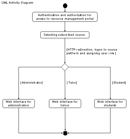
Figure 5‑3: UML activity diagram of the course
platform
connected to the resource management
portal.
LDAP Server and Clients
LDAP server
The functionalities of the LDAP server remain as described in Chapter
4 with the exception of the authentication. The
authentication and authorization infrastructure at the respective home organizations
now performs the authentication. A minor change has occurred regarding the
distinguished names of the users, split up into organizational branches before.
Now user entries remain in the same branch but are unique due to the
authentication and authorization infrastructure nomenclature in the form of
unique user identity @ home organization.
LDAP clients
Administrators access the respective directories where they
possess the administrative responsibility for the user data. Administrators
must not add user accounts manually but may add additional user information to
the existing entries. The module administrators can define the settings of the
reservation system: starting time of the first lot, the slot length, and the
period where he or she wants to add slots to the timetable of the reservation
system.
Interactions
with the LDAP directory
In this case, the higher-level user management system’s
database is the resource management portal’s database. The resource
management portal adds user accounts to the resource managements system’s
database. The user management system does not authenticate users, which access
through the resource management portal. The authentication tasks are reduced to
authenticate users writing to or readings of the database, such as the resource
management portal process with read and write permissions or the laboratory
portal process with read permission for the respective module. Administrators
add additional user information to existing accounts, and module data in the
resource management system’s database. Resource content providing
servers, the course platform, and the laboratory portals read out user data
meanwhile the laboratory portal also reads out the module data, i.e. the
current user and the timeslot duration. The reservation system reads out module
and user data from the resource management system’s database to display
the timetables with the module reservations. It writes into the resource management
system’s database to set timeslots and the current users of the modules.
Laboratory Portal Server
The laboratory portals used in the extended multifunctional
e-learning architecture fulfill the same tasks as in the multifunctional
e-learning architecture discussed in Chapter 4. The difference is that the laboratory portals use
the authentication functionality of the authentication and authorization
infrastructure Shibboleth and the respective home organizations and no more
with LDAP against the user management system’s database.
Figure
5‑4 depicts the UML sequence diagram and Figure 5‑5 the sequence diagram of a person accessing a
laboratory portal. In a first step, the person has to authenticate and
authorize with Shibboleth at the respective home organization. The first access
has to take place on the resource management portal as only the resource
management portal adds users to the resource management system’s
database. Upon a successful authentication, the user is authorized to access
the laboratory portal. The laboratory portal now checks if a reservation for
the user and module is available. If not, the user cannot access the hands-on training.
If yes, the user accesses the hands-on training web interface and selects the
devices he or she wants to access. During the hands-on training, the laboratory
portal queries the timetable at regular intervals or safes the slot lengths at
the beginning of the session and logs out the user when the session ends.
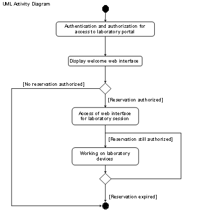
Figure 5‑4: UML activity diagram of a person accessing
a laboratory training.
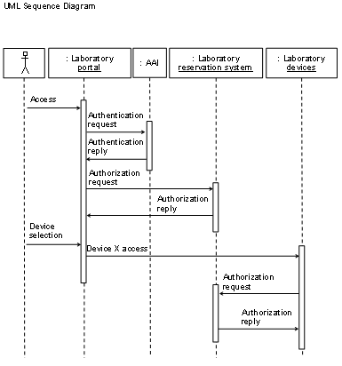
Figure 5‑5: UML sequence diagram of a person accessing
a laboratory training.
The laboratory devices behind the laboratory portal, the user
interactions with the reservation system and the laboratory portals as well as
the security aspects and the implementations are similar to those discussed in Chapter
4 with discussed the exceptions.
5.4 Discussion and Conclusions
The extended multifunctional e-learning architecture is a
further development of the multifunctional e-learning architecture. The
motivation for this development was the integration of the computer networks
laboratory into the Swiss-authentication and authorization infrastructure
Shibboleth. This extension represents a test for the extensibility of the
multifunctional e-learning architecture. Between higher-level user management
system and the multifunctional architecture, the resource management portal
architecture was interlaced. The user management system, the reservation
system, and the laboratory portals were further developed and integrated into
the extended architecture. The extended architecture is thus no longer as
independent as the original architecture but at the same time proves that the
original architecture can be adapted to special situations and extended in
specific directions. The most significant architectural change affects the user
authentication, now done by the higher-level user management system. The authorization
before getting access to the computer networks laboratory is also handled by the
higher-level user management system. The resource management portal represents
the entry point for course subscription as well as for each course access now.
This access procedure reduces most administrational tasks related to course
subscriptions to granting access or not on the resource management portal. The
portal writes user accounts into the course platform’s database and logs
users into the course platform. The portal also writes user accounts into the
LDAP database. Users are authorized against the LDAP database once in the course,
when accessing laboratory portals.
The implementations of the reservation system and the
laboratory portals were adapted to the user management system and now require
the Shibboleth target site installation for the authentication process. A
positive outcome is that the entire course is now single sign-on enabled and
requires only one login for users with cookie-enabled browsers.
A conclusion valid for both e-learning architectures is that
students may use the computer networks laboratory with only a few
preconditions: a low bandwidth Internet access and an actual web browser
supporting Java. Students from
The extended architecture could be enhanced by other higher-level
user management systems such as Diameter or a higher-level user management
system compliant to the Liberty Alliance. Only the future itself shows which higher-level
user management systems will be used in the e-learning market and thus is worth
to be integrated into the multifunctional e-learning architecture.
The extended architecture could be enhanced in many more directions;
most points have already been described in the outlook of the original
architecture. The integration of the resource management portal opens new possibilities.
In case the resource management portal would be enhanced by QoS information or
enabled to detect this information automatically, the e-learning content could
be adapted to this information. Particularly video streams could be provided in
several qualities by the web server. An adaptation of the content and the
laboratory portals could be the preparation of the screen for the resolution
the client can display.
For the processing of such additional information, it could be
necessary to replace the existing LDAP-based user management system by a
relational database. In the case of the extended architecture, this is no disadvantage,
as the most important aspect for the LDAP-based system no longer exists: the
possibility to connect directly to root LDAP databases for the user
authentication. The relational database could be used for other enhancements
too, such as the representation of multiple laboratory sessions of one type as
one unit in the reservation web front end or the integration of a virtual
group-building tool.
Another direction of a future development could be the
integration of the user management system on the resource management portal. An
advantage would be the reduced number of necessary servers.
6 Didactics of Computer
Networks Laboratories
This Chapter discusses a didactical framework and its implementations for teaching Internet-based computer networks laboratories [SJZB02b]. The Chapter also discusses the applied learning methods. The term traditional laboratory refers to in house teaching and the term e-learning to Internet-based or distance teaching. Chapter 6.2 starts with the analysis of didactic concepts commonly used in traditional computer networks laboratories. This analysis provides the required information, necessary for the development of the new didactical framework in the environment of e-learning, discussed in Chapter 6.3. The main motivation for the development of the new framework is to increase the teaching quality of e-learning courses compared to traditional courses. The didactical framework and approaches comprises well-known didactical methods but in a new composition. We applied the framework to a prototypical e-learning computer networks laboratory. Chapter 6.4 presents the usability feedback gathered from the students. In Chapter 6.5 we discuss and conclude the didactical framework and Chapter 6.6 gives an outlook to future didactical approaches in e-learning.
Traditional computer networks laboratories [SB02] exist in most
universities with computer science curricula. These laboratories consist of
network equipment and computers ready to use for students, which attend these
courses on-site. The audience of traditional laboratories almost only consists
of students living close to the university. Students can only perform the
exercises during office hours and they have to travel to the laboratory. We
analyzed a traditional laboratory and the existing traditional didactical approach,
as an exemplar approach found in traditional teaching, grown over the years. The
didactical concept of the exemplar traditional laboratory is very basic but a
de facto standard for all types of university hands-on trainings. It consists
of an intuitively applied teaching approach. Students have to auto didactically
learn and understand the necessary theory as the course material almost only
offers references to required and recommended literature.
The analyzed traditional laboratory consists of several modules,
as described in Appendix B. All the modules have the same didactical structure,
consisting of three major blocks:
- Pre laboratory section
In this section, the students get general
information about the module’s subject and a selection of required
readings, supplemented with recommended readings. Students have to solve subject
specific problems at the end of this section. With the exception of lecture
references and of the quiz at the end of the section, students have to study
the theory auto-didactically.
- Laboratory section
In this section, the students perform the hands-on
training in the laboratory. Good theoretical preparation is necessary, as the
presence time in the laboratory room should not exceed a certain number of
hours. During the hands-on training, the lecture notes and the tutors provide
only hints and not complete guides for solving the exercises. Students perform
the work in small groups and have enough time for learning by doing in a
trial-and-error process.
- Post laboratory section
In this section, the students have to solve exercises
related to the practical work done in the laboratory section. They use traffic
dumps and configuration and measurement logs of the laboratory work to
demonstrate their success in the hands-on exercises and to prove their
understanding of the learning module’s concept.
The didactical methods used in the analyzed traditional
laboratory are private study, references to readings, scripts, teamwork, essay
tests, learning by doing, trial-and-error learning, and discussion.
We observed the students of the
analyzed laboratory during their laboratory sessions and analyzed both, the
preparing homework and the post laboratory works. The analysis showed that
students must prepare the laboratory for performing the hands-on training successfully.
Many students did not prepare themselves sufficiently prior to the hands-on
training. Those in particular had significant problems solving the hands-on trainings’
exercises within a reasonable time. The same poorly prepared students had to
ask many questions to the tutors during the laboratory trainings.
Other students had already forgotten the theory learned in the
ordinary university lectures. Although most of the students studied computer
science, for many of them it was the first time they could set-up and work on
real network servers and routers. Most students liked the opportunity to work
on real network devices and to leave theoretical studies for a short time. The analysis
also showed that students especially liked hands-on work and that this is a
desired supplement to study curricula. Students did not like the
pre-laboratory. The theory should therefore be included in the trial-and-error
process of the laboratory section if possible.
The student groups were limited to two students and the
complete hands-on work was performed in the team. Students only performed the
preparative reading and learning independently. The analyzed computer networks
laboratory offers space for two teams simultaneously, and other students work
in the same room. This situation motivated many fruitful discussions about, but
not only, the laboratory work. Students learned that teamwork leads faster to
the goal, or in other words: altruism wins over egoism. They use the trial-and-error method instead of copying already
prepared configuration scripts, as observed in other lectures. This results in
a better understanding of the subject.
We had to split the laboratory time in slots and one group
could maximally occupy two timeslots due to a restricted number of laboratory
equipment. Consequently, students who skipped preparation and tried to
integrate it in the practical trial-and-error section could not succeed within
the estimated time. Accordingly, we supply hints at critical points of the
laboratory session to prevent blockades.
Students do not like if they
receive many readings and prefer an especially prepared lecture script. We
observed that some tasks are difficult for some students and simple for others.
Traditional laboratories fulfill the
expectations from students and tutors relative to what a computer networks
laboratory course must be.
6.3
Didactical Structure of an
E-Learning Laboratory
We assumed that the
didactics concept of this e-learning course must cover the education of
computer science students with finished basic studies. Students should be able
to work through a learning module within a predefined time. Students from other
disciplines (e.g. economics) who have knowledge lacks in certain topics of
computer science may need more time per module but have to find enough
additional resources to understand everything. The prototype course structure
developed reflects the intention to provide a common design to the e-learning
course. Without a common design, students loose too much energy with exploring
each learning module’s structure. Designers must avoid unnecessary
repetitions; else, students do not read the texts and skip important information.
This has led to a course design with a common introduction chapter for all modules
and an identical structure for each of the modules. The developed course
structure with the didactical framework has found its way into a didactics and
design guide for hands-on trainings oriented e-learning courses [SWVB03]. Appendix
C lists the didactically identical modules of the prototype course.
The common introduction chapter discusses the background and questions regarding the entire course. Figure 6‑1 shows a house that represents the e-learning course under whose roof single modules are stacked. The base of the house is the common introduction.
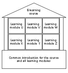
Figure 6‑1: The e-learning course elements.
In the first part, the
common introduction explains the course’s global objectives, the didactical
approach, and the course structure for students and tutors. The second part introduces
studying online for beginners; explains the course management system with the laboratory
reservation system, indicates external resources useful for the whole course, explains
the evaluation procedure, introduces discussion boards, explains the help system
and the surveys. All this information is part of the didactical framework in
which we intend to inform and prepare students as well as tutors to the single
learning modules.
Each of the learning
modules in the e-learning course has the same structure, consisting of four
sections. Section 1 introduces students to the module topic with a very brief abstract
and subsequently explains the goals of the module, and how to reach them. The
module is placed into the course context with its many other modules. A first
student task is to formulate own learning goals for the respective module. In section
2, students have to study the theory necessary for understanding the following
hands-on training section. There is at least one required reading of a
scientific article and a bunch of recommended readings. The next student’s
task is to write a personal synthesis. Subsequently students solve the
self-test and then proceed to the quiz. Tutors evaluate the quiz, which covers
the whole theory section. In section 3, students proceed to the hands-on section.
Students work on simulations, emulations, and real devices. The before learned
knowledge has to be applied in a trial-and-error procedure. In section 4, students write another
synthesis about the whole module topic and express in their own words what they
have learned. Then, they advance to the final quiz. In the quiz, results of the
hands-on training have to be integrated and general exercises solved.
The new didactical
framework for hands-on training oriented e-learning courses comprises several
well-known didactical methods, with a special emphasis on the knowledge association
on
- Logbook
The logbook’s task is
to replace the real logbook that exists in traditional laboratories.
The logbook is something
like a notepad and used in traditional laboratories. Students make all personal
notes, calculations, remarks, and draws into the logbook. In this way, the
logbook documents the personal learning procedure of each student. In case of
problems, tutors and students can go through the logbook to search for the
reasons of those problems.
- Learning Goals
The learning goals’
task is to define the learning activity and the goals to reach at the end of
each learning module.
Students need to have easy
understandable but as well clear formulated learning goals. Without learning
goals, students do not know what exactly they have to learn and memorize for
later. Learning goals also contain the evaluation procedures and the expected
quality of the results.
- Own Learning Goals
The own learning
goals’ task is to activate existing knowledge prior to start with the
main knowledge acquisition section.
In this didactical framework,
students have only read the learning module’s abstract and the learning
goals when they have to write down their own learning goals. With this task,
students reactivate and remember already existing knowledge and re-associate it
with the information they have about the module. Writing down the own goals
helps memorizing the new associations and prepares the start in the knowledge
acquisition section. At the end of a module, students can verify if the have
learned what they have expected before. For tutors these self-formulated learning
goals show what students expect from the module topic.
- Module Vicinity
Module vicinity’s
task is to locate a learning module in the context of the other learning
modules.
The e-learning course lists
its single modules in a certain order on an overview page but without numbering
the modules. Each of the modules is a in itself closed learning unit that can
be used inside or outside of the entire course. To provide an order for
students that work through the whole course, we introduce a vicinity map. This
map shows the recommended modules sequence for students who want to work
through the complete course. An icon represents each learning module and the icon
of the module in which the student is located at the time colorized.
- Mindmap
The Mindmap’s task is
to initiate students for a self-association of existing knowledge.
In Mindmaps such as shown
in Figure
6‑2 students find the module topic in the centre and from
there leave branches with theory (green) and practical (red) topics.
Neighboring modules are depicted in yellow balloons to show the close relation
to the module topic in the centre of the Mindmap. Students are animated to draw
own Mindmaps or to further develop the proposed map. By adding and labeling own
branches, students draw in a way they think, i.e. they write down how their
knowledge is associated in their mind. By watching their own associations they
can create new associations. Mindmaps help to recall knowledge within a short
time, for example before an exam, because they reflect their designer’s
knowledge.
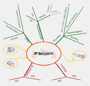
Figure 6‑2: Mindmap.
- Scientific
The scientific readings task is to introduce students in scientific
writing.
Scientific readings are a didactical
method used to accustom students to the way scientists communicate their
results. With the integration of such readings in each module, a part of each
module’s knowledge acquisition section is imparted in that way and the
understanding evaluated in the quizzes. Besides the required readings, there
are also recommended readings, representing a collection of text references,
and base as well as higher-level readings to the module’s topic.
- Personal Synthesis
The personal synthesis’ task is to associate knowledge
recently studied in the knowledge acquisition section.
The personal synthesis is a didactical method,
which helps to recall the already known but not present knowledge and to
associate it with recently learned knowledge. Students associate
their knowledge by writing an essay about a self-chosen topic of the theory
section. During the composition of such an essay in their own words, they pass
the whole knowledge acquisition section again and can thereby discover
unresolved problems as well as draw new conclusions.
- Self-Test
The self-test’s task
is to provide students with the possibility of a self-evaluation.
Self-tests help students measuring their knowledge
and discovering missing parts. Skilled students can bypass theory by solving
self-tests questions correctly. The self-test immediately provides results and
in case of wrong results points to a resource where the missing information can
be read. Providing a positive feedback even in case of a correct answer helps
students to return to a certain source text in case of doubts. Self-tests are
not graded nor reviewed by a tutor; they are a pure self-evaluation tool.
- Quizzes
The quizzes’ task is
to evaluate students’ work.
With quizzes, we analyze what students really have
understood of the lecture. A tutor grades quizzes. Quizzes consist of multiple
choice and essay questions.
- Discussion Board
The discussion
board’s task is to provide a communication platform.
In the discussion board, students communicate with
students or tutors. A tutor moderates the discussion board, solves open issues,
and keeps discussions in the area of the module’s topic. The board gives
eager students a chance to help others and they can thus deepen their own
knowledge.
- Schedule
The schedule’s task is to provide fast information
about the learning progress.
Figure
6‑3 shows the developed schedule. The schedule replaces
the missing orientation students normally have when reading a book. It helps
students to see where they stay and how much time they still have to invest.
The schedule is static and provides the expected duration in each of the
module’s sections. Students that are more skilled progress faster, less
skilled students who read additional information slower. It helps students also
to remain on track and not to loose themselves in additional readings.
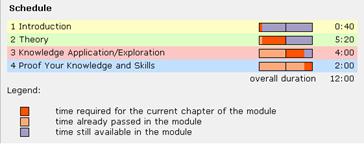
Figure 6‑3: Where to spend how much time.
- Help
System
The help systems task is to
provide a solution to every problem.
We designed the help system to offer around the
clock fast help in case of problems. The help system consists of several parts
put together in a certain order. The first place to look for help is in
frequently asked questions section. The second location to address to in case
of problems is the discussion board. It is likely that students find an answer
to their question or get one within a short time. Browsing in already solved
problems can give hints for the own problem. Tutors should extract important
questions after each course cycle and summarize in the frequently asked
questions section. If the discussion board does not cover the problem, students
can send an Email to the module tutor. As a last solution, students can call a
hotline number. Only by this filtering method, the hotline can be operated
without having students calling all the time. Our help system can be
represented as a help pyramid, shown in Figure
6‑4.

Figure 6‑4: The help pyramid.
- Interactive
Animations
The interactive animation’s task is to
present theory in multiple dimensions.
Not all students learn the same way. Some students
fully understand theory imparted as plain text, others need additional figures
and some animations. Each supplementary dimension added to plain text activates
a further brain region. Thus by adding interactive animations, multiple brain
regions are activated to solve a problem.
- Notes
Tool
The notes tool’s task is to enable students to
write directly into the text.
The notes tool should enable student to write their
text specific notes directly into the text. This is necessary to allow students
to use their traditional learning style.
The framework of the above-discussed methods contains text
readings, references to recommended readings, self-test, self-evaluation, quiz,
trial-and-error learning, and learning by doing, guided practical working, and
discussions on discussion boards, reflections, mind map, logbook, video
sequences, interactive animations, and schedule.
We implemented the didactical framework in the e-learning
computer networks laboratory and gathered feedback from the students who worked
through the course. About sixty third-year university students participated in
the test. All had to return feedback forms at the end. A majority of the
students was computer science students and had already finished their basic
studies. Tutors and students regularly communicated and tutors collected any
form of feedback. It was surprising to see that also computer science students
experienced troubles caused by the different web browsers and operating systems.
During the course, students got response by Email or telephone from a tutor
within zero to six hours in case of problems not answered in the frequently
asked question’s section or the discussion board. Tutors revised the
discussion board on a regular basis of about four times a day. Students
appreciated the short response times. There was negative feedback concerning
the hardly understandable user guidance of the commercial course platform,
hosting the learning content. The course platform earned negative feedback not
only because of the non-intuitive user guidance but also because it uses Java
scripts. Java scripts provoked many errors in the different browsers and versions.
As expected, the non-existence of teamwork similar to on-site
teamwork in traditional laboratories resulted in many complaints. Many students
wanted to have more interactive content and more practice-related examples in
the theory section. Many students liked to printout the theory section and
there was a lot of negative feedback until we offered the theory as a
downloadable and printable file. Students positively mentioned the high
availability of the laboratory equipment and the fast download speed of the
course material.
Students liked the integration of different types of
interactive technology and the resulting course, such as with interactive
animations. Students liked to work remotely on real network hardware, to
configure routers, to do hands-on work. Students described the experience with
real network hardware as very fascinating. The framework of the course platform
that leads through the course and additional windows with connections to the laboratory
devices imparted the impression of a guided working with a high degree of work freedom.
Students liked to solve problems in a trial-and-error process as they are
convinced that knowledge gained in this way stays in mind for a longer time.
The quizzes consisted of multiple choice and essay questions. Students liked
the mix but preferred multiple-choice questions. Students often mentioned that
the learning content was well adapted to the learning objectives. Students were
thereby motivated to read through, and not to skip, the theory part. Students
found that the course was comprehensively documented. This seemed to be very
stimulating for the learning behavior. Most students liked the independence of
time and place of work, although in the final discussion, one student
complained about the expansion of work times into free times such as evenings
and weekends.
Not only the whole literature should be downloadable and printable, the exercises and solutions as well should be downloadable and printable. One student missed a module résumé on one A4 page. Students liked the information provided by the introduction chapter with abstract and storyboard. The analysis of the timetable showed that a majority of students liked to work in the evening and on weekends.
6.5 Discussion and Conclusions
The didactical aspects of e-learning, especially in
hands-on trainings oriented computer network laboratories are different to
didactical aspects of traditional, in house teaching. Our developed didactical
framework can be generally applied and adapted for e-learning resources, for
example the separation of common material of all learning modules into a global
introduction chapter, the students’ preparation for the study topic in
the introduction chapter of each module and the self reflections tasks about
the topic. The introduction chapter introduces students in the topic and they receive
a first portion of study matter. The formulation of their own goals requires a
deep reflection about already learned stuff related to the module topic and
allows first re-associations of existing knowledge with the new input. Prepared
like that students proceed to the theory chapter and conclude the chapter with
quizzes and a reflection about the theory. Again, this reflection deepens much
more the knowledge than any quiz, associating new and existing knowledge
together, fostered by the expression in own words. The quiz and the reflection
at the end of the practical chapter aim the same goals. This second reflection
now comprises the whole module, from the beginning up to the end. Students
re-pass the module topic as a whole and work-up the entire study matter.
Students’ feedback confirmed that topics elaborated in this way show a
higher sustainability. Special developed concepts are dedicated to hands-on trainings
oriented courses, such as the logbook. The logbook is a testimonial of
students’ work. Students appreciated the supporting function of the logbook
in the case of troubles with the hands-on trainings.
Generally, we noticed that preparation work is urgently
needed for the students to perform hands-on exercises successfully. We
discovered that many students did not prepare themselves sufficiently prior to
the practical work. It is very important that students successfully pass the
quiz before entering the hands-on trainings. Only well prepared students managed
to work through the exercise tasks within a reasonable time. The same students
had to ask many questions to the tutors during the laboratory session. Our didactical
framework with the mandatory reflection tasks ensures that students do not skip
parts of the knowledge acquisition section. For the same reason, we decided to evaluate
all of the tasks.
The disfavor students showed for the selected course platform
may have several reasons. The course platform limits users to few actions and
it is difficult to promote cognitive learning styles in this environment. It is
not possible to use markers in the selected course platform. This is a heavy
disadvantage compared to paper copies. Students are used to notes and markers.
Also next generation students will have to use both of them in their learning
process.
The switch from traditional to e-learning showed that
students like to see network equipment in reality. Hence, we recommend
organizing laboratory visits at the beginning of an e-learning course, giving
the students a feeling about the hardware they are going to work on. The
available on-line material has been a problem in some cases since as still a
lot of good teaching material is only available as hardcopies. Copyright issues
prohibit distributing digitized copies among the students.
E-learning courses are a welcome supplement to traditional
study curricula but not a full replacement. None of our students could imagine
studying just with e-learning resources. We conclude that students need the
contact with real tutors and real classmates as well as the contact with
lecture rooms. Otherwise, the community feeling gets lost and interest in studying
decreases.
Nowadays it is possible to offer e-learning resources operated
by a network of content providers. An advantage of such e-learning grids is
that they require only one didactical framework, which the partners elaborate.
Thus, the number of students in the courses can be increased, and the workload
for developers and tutors decreased. Swiss German people designed and
implemented our prototype course modules, now open for students from different
cultures. Therefore, designers have to remember the different cultural sensations,
comprehensions, and learning styles.
In one course run of the evaluation, we allowed teamwork in the
form of two students sitting in front of the same computer during the hands-on trainings.
Students appreciated this form of teamwork but many misunderstood the teamwork
allowed in the hands-on trainings only and shared the whole work, i.e. both did
only half of the course. It is not easy to answer the question why students
prefer teamwork to single work. It is out of doubt that teamwork is necessary
in most areas of life and that teamwork simplifies learning processes. However,
it is obvious too, that free riders misuse teamwork. Educators have the task to
accompany students throughout their studies. Free riders are better involved in
the studies if they are forced to make the tests and exercises alone. Another
means to involve free riders is the generation of tests consisting of randomly
generated quizzes with an abundant underlying questions base.
From the didactical point of view, there are still many obstacles
to overcome until reaching the same high level of education as in traditional
courses.
The developed didactical framework builds a solid base for
e-learning courses but with more time and money, substantial improvements could
be realized. One area where improvements would ease studying is everything
related to the web interface. Usability could be improved by providing more
information about the progress students make throughout the course. The actual
static schedule should be replaced by a dynamic schedule where default time
values and real values could be compared. This would allow students to know
more about their current study progress. The schedule could be more realistic
also by including the times of the finished and yet to do exercises and
quizzes. We suggest creating an additional browser window in the course
platform. This window should not only display the current schedule but also a
list of open tasks such as exercises, essays, and quizzes.
Course platforms could get closer to the traditional learning
style by providing virtual text markers. The course platform would have to remember
marked text and additionally offer the possibility to extract highlighted text.
We also recommend developing a better notes tool, where the notes can be pinned
directly onto the text and reappear on click (post-it style). The author does
not know any course platforms, which provides the possibility for students to
download the courses at any stage of study progress, including personal notes,
quizzes, essay and more. Without such functionality, students cannot keep their
studies at hand. Logins for course platforms rarely exist longer than a study
career lasts. This is a major obstacle if course material should remain
available for students in a similar manner as in traditional learning.
Course platforms allow tutors to subscribe students to courses.
This is fine if a course is only used once and never again. Most e-learning
courses are re-used or opened to different schools at the same time. It would be
necessary to implement the possibility to maintain a class list for each course
with the option to open multiple classes.
Current e-learning courses are static constructs. A future
development could lead to dynamically created courses where the content is
adapted to the student. At the beginning of a course could be a test and the
results of the test then trigger the content preparation. The dynamic content
should contain checkpoints to verify if the student understood the content and
then again adapt the remaining content. The base for such an individual content
compilation is a detailed description of each part of the content itself. A
preferable choice is the open standard XML, where various e-learning extensions
exist. For the content preparation a generic system should be designed where it
is not necessary to prepare each test and control question manually. Artificial
intelligence could enable such a system to achieve these high goals.
Future e-learning courses should integrate something like a
virtual team market place, where students can anonymously look for teammates.
The importance of this component is much higher if students, who do not know
each other personally from real university lectures, use the course. The market
place should allow generating user profiles with important information about
thins such as preferred study times and study state or test results.
It is necessary to update e-learning courses regularly due to
the ongoing progress in technical and didactical aspects. New didactical methods
must be integrated and new teaching dimensions achieved for example with the
integration of audio and video applications. Such applications should become
common tools for Internet users if bandwidth continues to increase as in the
past and computers continuously got more powerful. When a greater community uses
microphones and cameras, it will be possible to design virtual classrooms
allowing social contacts much closer to real life.
7 Synopsis
The four main Chapters of
this thesis, Chapters 3, 4, 5 and 6, each ended with a Discussion and Conclusions Chapter
and a subsequent Outlook Chapter. Each of these Chapters was directly related
to the before discussed topic and did not deeply associate the different
Chapters. The Synopsis starts with a Summary of the whole work, goes on with a
global Discussion and Conclusions, and gives an Outlook for the complete work.
The presented work started with the design and an analysis of a
traditional computer networks laboratory, where students attend the lecture in
groups. We performed the analysis of this exemplar traditional computer
networks laboratory to reveal the technical and didactical processes of this
course as a base for the design of a distributed e-learning architecture for an
e-learning computer networks laboratory.
The designed distributed architecture addresses questions
related to the management of the user access for students, tutors and
administrators, as well as for the access to the laboratories with limited
numbers of hardware resources. We called the architecture multifunctional
e-learning architecture. It provides all the necessary elements, and interfaces
for the operation of e-learning resources with the exception of the e-learning course
platform, responsible for the provisioning of e-learning documents, quizzes,
and communication functions.
The architecture describes a lightweight directory access
protocol-based resource management system for distributed content providing in
e-learning grids. With this architecture, it is possible to build a grid of
geographically distributed hands-on trainings laboratories with third party equipment,
such as an exemplarily implemented laboratory with routers and hosts represents.
The architecture also addresses the question of how to interconnect the architectural
element resource management system and the integrated user database with the
lightweight directory access protocol directories of other organizations. We
also discussed how third party user management systems could directly create
user accounts in the resource management system. The architecture comprises a
user and resource management system, laboratory portals for the connection of
third party laboratory devices and whose protection of threats from the
Internet, geographically distributed content servers and a certificate
authority.
We prototypically implemented the architecture with the
exception of the certificate authority and analyzed the interaction of the
single elements. The lightweight directory access protocol-based e-learning
architecture proved that it is possible to operate a geographically distributed
e-learning course with a focus on hands-on trainings laboratories over the
Internet with no special software requirements on the client side.
The educational environment has started to form educational
federations and establish federation-wide authentication and authorization
infrastructures. This was the initiator for the research on how to address
these changes with the multifunctional e-learning architecture. The conclusion
was that we have to design a broker between these authentication and authorization
infrastructures and any kind of resource, addressing the open questions of
information flow from the authentication and authorization infrastructures
towards not especially adapted resources. The resulting architecture describes
such a broker with modular, reusable, and adaptable interfaces, responsible for
the information exchange towards authentication and authorization
infrastructures on one side and towards resources on the other side. We called
the broker resource management portal and it comprises user management based on
user information attributes, collected from users and authentication
infrastructures, resource management functionalities, the possibility to
generate local user accounts, accounting functionalities and inter-community
communication features, allowing course participants to communicate, and
exchange documents on the portal.
The succeeded prototypical implementation integrates interfaces
to one authentication and authorization infrastructure and to various
resources. The prototypical implementation proved the architecture’s
concept of interconnecting not especially designed resources with
authentication and authorization infrastructures and of adding supplementary
functionalities such as user and resource management.
The fusion of the multifunctional e-learning architecture with
the resource management portal architecture led to the extended multifunctional
e-learning architecture. It addresses the questions related to the integration
in authentication and authorization infrastructures. The resulting architecture
depends on third party user management systems, such as represented by the
resource management portal’s local user accounts or the users originating
from higher-level user management systems.
The prototypical implementation of this architecture additionally
contains single sign-on functionality for users and offers an interface to a commercial
course platform. In the multifunctional e-learning architecture, the higher-level
user management system generates user accounts in the resource management
system and in the course platform, whereas in the extended architecture the
resource management portal generates the user accounts and logs users into the
course platform. The extended architecture shows the flexibility of the multifunctional
e-learning architecture regarding its adaptability to new requirements. The
concept of operating an e-learning grid with a higher-level user management
system, responsible for authentication issues on all course resources and an
own resource management system, responsible for authorization issues with an
interlaced broker could be proved with the prototypical implementation.
For the prototypical implementation of the e-learning computer
networks laboratory, we have designed a didactical framework, which addresses
the questions arising in this form of distance learning. The didactical framework
is applicable to most e-learning resources and discusses especially how to
activate students’ thinking processes, how to foster existing knowledge,
and how to associate newly acquired with existing knowledge. The framework
comprises well-known didactical methods but groups them together in a new way,
with a special focus on hands-on trainings oriented e-learning courses.
We summarized the didactical framework in a document, which
enables professionals without prior experience in didactics or web design to
produce state-of-the-art e-learning courses with a focus on hands-on training.
Didactic specialists can adapt the framework to other e-learning projects. Students’
feedback about the usability revealed that they assume studying in the
didactical framework-based e-learning computer networks laboratory results in a
better understanding of the learning matter and a higher sustainability
compared to traditional computer networks laboratories.
Throughout the presented work four outlook Chapters completed
each of the main Chapters. This outlook Chapter tries to give an outlook beyond
the next possible extension steps of the presented architectures.
The discussed architectures all ease the access to resources in
the Internet. The common goal is to disburden the persons involved in resource
access, such as the users, who have to remember many resource access credentials
and try to ease the credential management with the use of simple passwords or
to use the same password for many different resources. Moreover, the
architectures disburden the resource administrators who have to issue resource
access credentials and to support the users.
The discussed architectures indeed ease the credential
management as the same credentials in the multifunctional e-learning architecture
can be used for the access to an e-learning grid consisting for example of many
computer networks laboratory resources. In the case of the extended
multifunctional e-learning laboratory, the resource access credentials are
valid for a larger user community, also called federation. Still, many resources
will never join such a federation and there will always be federations, which
are not interconnected.
The technically smartest authentication and authorization
system uses unique identifiers for each individual. A connection between these
unique identifiers and the individuals should be technically established. A set
of distributed but interconnected databases could be used for the resources to
query for the owner of a user credential, for example for retrieving billing
information. All the resources would have to authenticate users with these
unique credentials. For this to happen, globally available credential readers
must be available first, for example finger print or iris readers. All the
potential users would have to register in one of the distributed databases with
their personal data.
Such a system would ease the resource access and administration
significantly. The challenge in the design of the system is to find a way for
protecting the user’s privacy. On the resource level, this can be
achieved by delegating the user authentication to a third party organization,
or as in authentication and authorization infrastructures usual, to the home
organization of the respective user. The resources would have to communicate
with the users over the home organizations or to retrieve more user information
by the home organization if the users agree. In such a system, users would have
to trust their home organizations regarding user privacy protection.
Technically there exists no way to prevent non-authorized persons from reading
out user and resource usage data in these home organizations. Considering that
all resource should be integrated in the system, it is hardly imaginable that
Orwell’s vision of the transparent human being would not become reality.
It is much more realistic that the described authentication and
authorization infrastructures such as Shibboleth, Liberty Alliance, or Diameter
will be extended to daily applications, for example for the integration of
finger print scanners in physical access systems, or copy machines. This would
allow the authentication and authorization with the same home organizations as
used for the web authentication and authorization. Additional user information
attributes will be stored in the home organization’s databases. The new
devices will have to be enhanced with a procedure for the selection of the home
organizations and the definition of the attribute release policy.
An already ongoing fusion of authentication and authorization
infrastructure with computational grids such as in the case of Shibboleth with
several grids will probably increase in the future. Grids can profit from the
authentication and authorization functionalities provided by the authentication
and authorization infrastructures, such as it happened in our extended
e-learning architecture.
A Chapter of this thesis discusses a didactical framework for
e-learning resources. The framework makes use of the currently and for a
majority of students available didactical methods. These methods allow the
teaching of e-learning courses in an acceptable way, although many improvements
will be possible in future.
The framework comprises interactive animations, which open a
further approach to the understanding of learning matter. The production of
such two dimensional animations is currently possible but time consuming. For
the future, tools for the production of three dimensional, interactive animations
in an easy way have to be invented. These tools should also ease the
integration of audio information. The generation of such animations should not
get more complicated than it is for two-dimensional animations.
Enabling real teamwork is another task for the future. Audio
and video transmissions for all partners of an exercise or course module must
be developed in such a way that e-learning users can easily use them. The increase
of bandwidth in the past indicates that at least the transmission problem will
be solved in the future. However, clever systems for the video and audio
transmission management in courses have to be elaborated. Parallel private
communications should be possible between single users and user groups. It is
also necessary to investigate systems for parallel teamwork in e-learning
laboratories, for example for configuring laboratory devices together.
List
of Figures
Figure 1‑1: E-learning architecture elements......................................................................................... 5
Figure 2‑1: Single certificate authority.................................................................................................. 21
Figure 2‑2: Certificate lookup with one certificate authority.......................................................... 22
Figure 2‑3: Hierarchical certificate authorities................................................................................... 23
Figure 2‑4: Cross certification with two certificate authorities...................................................... 24
Figure 2‑5: Trust lists.................................................................................................................................. 25
Figure 2‑6: Kerberos authentication....................................................................................................... 29
Figure 2‑7: Kerberos inter-realm connectivity..................................................................................... 31
Figure 2‑8: IP packet after applying AH in transport mode........................................................... 35
Figure 2‑9: IP packet after applying ESP in transport mode........................................................... 35
Figure 2‑10: IP packet after applying ESP in tunnel mode.............................................................. 36
Figure 2‑11: SSL/TLS principle.............................................................................................................. 37
Figure 2‑12: LDAP tree............................................................................................................................... 42
Figure 2‑13: Attribute definition schema.............................................................................................. 44
Figure 2‑14: Object class definition schema........................................................................................ 44
Figure 2‑15: Example ldif file................................................................................................................... 45
Figure 2‑16: Alias entry............................................................................................................................. 45
Figure 2‑17: Two directories for two branches................................................................................... 46
Figure 2‑18: Referral entry........................................................................................................................ 46
Figure 2‑19: UML sequence diagram for a referral lookup............................................................. 47
Figure 2‑20: Shibboleth architecture...................................................................................................... 51
Figure 2‑21: PAPI architecture................................................................................................................. 54
Figure 2‑22: RADIUS protected network access................................................................................. 55
Figure 2‑23: Diameter protected network access................................................................................ 57
Figure 2‑24: Liberty Alliance architecture............................................................................................ 59
Figure 2‑25: UML sequence diagram of the Liberty Alliance
mechanisms................................ 60
Figure 2‑26: Layout of the traditional laboratory............................................................................... 67
Figure 3‑1: Typical AAI environment with the resource management
portal........................... 74
Figure 3‑2: The resource management portal at a resource
provider’s site................................ 76
Figure 3‑3: Interaction diagram for connecting users....................................................................... 77
Figure 3‑4: Attributes release and request............................................................................................ 78
Figure 3‑5: Resource management portal with interfaces to AAI and
resources..................... 80
Figure 3‑6: The resource management portal’s environment......................................................... 81
Figure 3‑7: The functional parts of the resource management portal.......................................... 82
Figure 3‑8: Resource management portal architecture’s user
information attributes flow... 83
Figure 3‑9: UML activity diagram for resource management portal
configuration flows..... 84
Figure 3‑10: UML sequence diagram for the resource management
configuration flows..... 85
Figure 3‑11: Interfaces to AAI.................................................................................................................. 86
Figure 3‑12: Interface to resource............................................................................................................ 87
Figure 3‑13: UML activity and sequence diagrams for access to
unprotected resource......... 88
Figure 3‑14: UML activity diagram for access to cookie protected
resource.............................. 89
Figure 3‑15: UML sequence diagram for access to cookie protected
resource........................... 89
Figure 3‑16: UML activity diagram for access to user name and
password protected resource. 90
Figure 3‑17: UML sequence diagram for access to user name and
password protected resource. 91
Figure 3‑18: UML activity diagram for the access to resource by
means of a shared secret.. 92
Figure 3‑19: UML sequence diagram for the access to resource by
means of a shared secret. 92
Figure 3‑20: Synchronous
versus asynchronous community interactions................................ 93
Figure 3‑21: Community interaction features..................................................................................... 94
Figure 3‑22: Several authorization levels in resources..................................................................... 96
Figure 3‑23: Redirection processes to get to a resource.................................................................... 99
Figure 3‑24: UML use case diagram for resource hosting............................................................. 100
Figure 3‑25: UML use case diagram for resource subscription................................................... 101
Figure 3‑26: Resource management portal’s web interface.......................................................... 102
Figure 3‑27: Resource management portals’ sample .htaccess
file............................................ 104
Figure 3‑28: Resource management portal’s system diagram..................................................... 106
Figure 3‑29: UML class diagram for the resource management
portal’s database............... 108
Figure 3‑30: Performance measurement testbed.............................................................................. 110
Figure 3‑31: Full access, 300 MHz, internal page............................................................................ 112
Figure 3‑32: Full access, 1 GHz, internal page................................................................................. 112
Figure 3‑33: CPU load full access, 300 MHz, internal page......................................................... 113
Figure 3‑34: CPU load full access, 1 GHz, internal page.............................................................. 113
Figure 3‑35: Apache & MySQL CPU load full access, 300 MHz,
internal page..................... 114
Figure 3‑36: Apache & MySQL CPU load full access, 1 GHz,
internal page.......................... 114
Figure 3‑37: Memory load full access, 300 MHz, internal page.................................................. 115
Figure 3‑38: Memory load full access, 1 GHz, internal page....................................................... 115
Figure 3‑39: Increasing access, 300 MHz, internal page............................................................... 116
Figure 3‑40: Increasing access, 1 GHz, internal page.................................................................... 116
Figure 3‑41: Detail of increasing access, 300 MHz, internal page.............................................. 117
Figure 3‑42: Detail of increasing access, 1 GHz, internal page................................................... 117
Figure 3‑43: CPU load of detail of increasing access, 300 MHz,
internal page...................... 118
Figure 3‑44: CPU load of detail of increasing access, 1 GHz,
internal page........................... 118
Figure 3‑45: Apache & MySQL CPU load of detail of increasing
access, 300 MHz, internal page. 119
Figure 3‑46: Apache & MySQL CPU load of detail of increasing
access, 1 GHz, internal page. 119
Figure 3‑47: Memory load of increasing access with 300 MHz, internal
page....................... 120
Figure 3‑48: Memory load of increasing access with 1 GHz, internal
page............................ 120
Figure 3‑49: Full access with 300 MHz, external page.................................................................. 122
Figure 3‑50: Full access with 1 GHz, external page........................................................................ 122
Figure 3‑51: CPU load during full access with 300 MHz, external
page................................. 123
Figure 3‑52: CPU load during full access with 1 GHz, external page....................................... 123
Figure 3‑53: Apache & MySQL CPU load, full access with 300 MHz,
external page........... 124
Figure 3‑54: Apache & MySQL CPU load, full access with 1 GHz,
external page................ 124
Figure 3‑55: Memory load, full access with 300 MHz, external page........................................ 125
Figure 3‑56: Memory load, full access with 1 GHz, external page............................................. 125
Figure 3‑57: Increasing access with 300 MHz, external page...................................................... 126
Figure 3‑58: Increasing access with 1 GHz, external page........................................................... 126
Figure 3‑59: Detail of increasing access with 300 MHz, external
page.................................... 127
Figure 3‑60: Detail of increasing access with 1 GHz, external page.......................................... 127
Figure 3‑61: CPU load of detail of increasing access with 300 MHz,
external page............. 128
Figure 3‑62: CPU load during detail of increasing access with 1 GHz,
external page........ 128
Figure 3‑63: Apache & MySQL CPU load of detail of increasing
access with 300 MHz, external page. 129
Figure 3‑64: Apache & MySQL CPU load of detail of increasing
access with 1 GHz, external page. 129
Figure 3‑65: Memory load of increasing access with 300 MHz, external
page...................... 130
Figure 3‑66: Memory of increasing access with 1 GHz, external page..................................... 130
Figure 4‑1: The architecture and the possible connections.......................................................... 143
Figure 4‑2: UML activity diagram for the course platform roles................................................. 147
Figure 4‑3: UML activity diagram of a person accessing a laboratory
training..................... 150
Figure 4‑4: UML sequence diagram of a person accessing a laboratory
training.................. 151
Figure 4‑5: UML use case diagram for student access................................................................... 152
Figure 4‑6: UML use case diagram for resource management..................................................... 153
Figure 4‑7: UML use case diagram for module management...................................................... 154
Figure 4‑8: UML sequence diagram for students’ booking
interactions................................... 155
Figure 4‑9: UML sequence diagram for students’ lab portal
interactions................................ 156
Figure 4‑10: Implemented architecture with course platform...................................................... 158
Figure 4‑11: DN for student data.......................................................................................................... 159
Figure 4‑12: DN for module data.......................................................................................................... 159
Figure 4‑13: DN for timetable data....................................................................................................... 159
Figure 4‑14: DN for staff data................................................................................................................ 159
Figure 4‑15: LDAP directory structure................................................................................................ 160
Figure 4‑16: Module reservation web interface................................................................................ 161
Figure 4‑17: From traditional to e-learning....................................................................................... 163
Figure 4‑18: Portal server and laboratory devices........................................................................... 164
Figure 4‑19: IP Security hands-on training....................................................................................... 166
Figure 4‑20: User interactions with management system and portal........................................ 167
Figure 5‑1: Comparison of user login.................................................................................................. 176
Figure 5‑2: Dependent multifunctional e-learning architecture................................................. 177
Figure 5‑3: UML activity diagram of the course platform connected to the resource management portal. 182
Figure 5‑4: UML activity diagram of a person accessing a laboratory
training..................... 184
Figure 5‑5: UML sequence diagram of a person accessing a laboratory
training.................. 184
Figure 6‑1: The e-learning course elements....................................................................................... 191
Figure 6‑2: Mindmap............................................................................................................................... 193
Figure 6‑3: Where to spend how much time..................................................................................... 194
Figure 6‑4: The help pyramid................................................................................................................ 195
List
of Tables
Table 1‑1: E-learning architecture elements........................................................................................... 5
Table 2‑1: Comparison of PKI models................................................................................................... 27
Table 2‑2: Advantages and disadvantages of Kerberos................................................................... 32
Table 2‑3: Comparison of Transport Technologies........................................................................... 40
Table 2‑4: Set of standardized LDAP attributes................................................................................. 43
Table 2‑5: Advantages and disadvantages of LDAP........................................................................ 48
Table 2‑6: Comparison of Shibboleth and Liberty Alliance features........................................... 58
Table 2‑7: Comparison of authentication and authorization technologies............................... 63
Table 5‑1: Comparison of original and extended architecture.................................................... 175
List
of Abbreviations
AA Attribute
Authority
AAA Authentication,
Authorization, and Accounting
AAI Authentication
and Authorization Infrastructure
AAP Attribute
Acceptance Policy
ASP Active
Server Pages
AH Authentication
Header
AQH Attribute
Query Handle (AQH)
ARP Attribute
Release Policy
CA Certificate
Authority
CRL Certificate
Revocation List
Clubs A club is a group of
organizations who agree to exchange attributes using the SAML/Shibboleth
protocols and abide by a common set of policies and practices.
DARPA Defense
Advanced Research Projects Agency
DNS Domain
Name Service
DOD Department
of Defense
DS Directory
Service
DSL Digital
Subscriber Line
ESP Encapsulating
Security Payload
FAQ Frequently
Asked Questions
HS Handle
Service
FAI Fully
Automatic Installation
HTTP Hypertext
Transfer Protocol
IETF Internet
Engineering Task Force
IMS Institutional Management
System
http://www.imsproject.org/
IKE Internet
Key Exchange
IP Internet
Protocol
IPC Inter-Process
Communication
ISAKMP Internet
Security Association and Key Management Protocol
KDC
LDAP Lightweight
Directory Access Protocol
LDAPS Lightweight
Directory Access Protocol over SSL
MACE Middleware
Architecture Committee for Education
MIT Massachusetts
Institute of Technology
MTA Mail Transfer Agent
MySQL My Structured Query Language
Open Source relational database management system that uses Structured Query
Language
NAS Network Access Server
OASIS Organization for the
Advancement of Structured Information Standards
OpenSAML Open
Security Assertion Markup Language
http://middleware.internet2.edu/opensaml/
OSI Open
Systems Interconnection
PAPI Point
of Access to Providers of Resources
PAM Pluggable
Authentication Module
PHP Hypertext
Preprocessor
PKI Public
Key Infrastructures
PoA Point
of Access in PAPI
PPP Point
to Point Protocol
Pubcookie ->
WebISO
RA Registration
Authority
RADIUS Remote
Authentication Dial-in User Service
RIP Routing
Information Protocol
RM Resource
Manager
RMI Remote
Method Invocation
RPC Remote
Procedure Call
SA Security
Association
SAML Security
Assertion Markup Language
http://www.oasis-open.org/committees/security/
SHAR Shibboleth
Attribute Requester
Shibboleth Shibboleth \Shib"bo*leth\, n.
[Heb. shibb[=o]leth an ear of corn, or a stream, a flood.]
SHIRE Shibboleth
Indexical Reference Establisher
SMS Short
Message Service
SNMP Simple
Network Management Protocol
SOAP Simple
Object Access Protocol
SPD Security
Policy Database
SPI Security
Parameter Index
SSL Secure
Sockets Layer
SSO Single-sign
on
TACACS Terminal Access Controller Access Control
System
TGT Ticket-Granting-Ticket
TLS Transport
Layer Security
Tomcat Tomcat is the servlet
container that is used in the official Reference Implementation for the
JavaServlet and JavaServer Pages technologies.
USB Universal
Serial Bus
VITELS Virtual Internet and
Telecommunications Laboratory of
WAYF Where
Are You From? Server in Shibboleth
WebISO Web
Initial Sign-On
http://middleware.internet2.edu/webiso/
W3C World
Wide Web Consortium
XDR External
Data Representation
Bibliography
ABDG97 D.
Anderson, S. Bowyer, J. Cobb, D. Gedye, W.T. Sullivan and D. Werthimer: A New
Major SETI Project Based on Project Serendip Data and 100,000 Personal
Computers. Astronomical and Biochemical Origins and the Search for Life in the
Universe, Fifth Intl. Conference on Bioastronomy, 1997
AK00 A.
L. Costa and B. Kallick: Getting
into the Habit of Reflection, Educational
Leadership. Vol. 57, No. 7 Sustaining change, April 2002, pp. 60-62
AL94 P.
Albitz, and C. Liu: DNS and BIND. O'Reilly & Associates, Inc.,
BBCC04 A.
Bavier, M. Bowman, B. Chun, D. Culler, S. Karlin, S. Muir, L. Peterson, T.
Roscoe, T. Spalink and M. Wawrzoniak. First Symposium on Network Systems Design
and Implementation (NSDI), March 2004
BBKS03 F.
Baumgartner, T. Braun, E. Kurt, M.-A. Steinemann and A. Weyland: Implementation of a Distance Learning Module
Based on Emulated Routers. Kommunikation in verteilten Systemen
(KiVS03),
BC95 T.
Berners-Lee and D. Connolly: HyperText Markup Language Specification 2.0, RFC
1866, November 1995
BD97 G.
Banga and P. Druschel: Measuring the Capacity of a Web Server. USENIX Symposium
on Internet Technologies and Systems,
BEFK00 R. Butler, D.
Engert, I. Foster, C. Kesselman, S. Tuecke, J. Volmer, and V. Welch: Design and
deployment of a national-scale authentication infrastructure. IEEE Computer, Vol. 33(12), pp.
60–66, 2000
BEKL00 D.
Box, D. Ehnebuske, G. Kakivaya, A. Layman, N. Mendelsohn, H. Nielsen, S. Thatte
and D. Wiener: Simple Object Access Protocol (SOAP) 1.1. World Wide Web
Consortium (W3C), May 2000
BFF96 T.
Berners-Lee, R. Fielding and H. Frystyk: Hypertext Transfer Protocol -
HTTP/1.0. RFC 1945, May 1996
BFIM98 T. Berners-Lee, R. Fielding, U.C.
Irvine and L. Masinter: Uniform Resource Identifiers (URI): Generic Syntax.
April 1998
Bg04 G.
Butera: Accounting and Information
Exchange Services on a Resource Management Portal. Diploma Thesis, May
2004
BS03 T.
Braun and M.-A. Steinemann: The
Virtual Internet and Telecommunications Laboratory of
BSW03 T.
Braun M.-A. Steinemann, and A. Weyland: VITELS
- An e-Learning Course on Computer Networks and Distributed Systems. SWITCH Journal 2/2003, p32-35
Bt99 T.
Braun: IPnG, Neue Internet-Dienste und virtuelle Netze. dpunkt Verlag, April
1999 ISBN 3-920993-98-5
Bv45 V.
Bush: As we may think. The Atlantic Monthly, 1945
Cb96 B.
Carpenter: Architectural Principles of the Internet. RFC 1958, June 1996
Cd88 D.
CDKM02 F.
Curbera, M. Duftler, R. Khalaf, N. Mukhi, W. Nagy, S. Weerawarana: Unraveling
the Web Services Web - An Introduction to SOAP, WSDL, and UDDI. IEEE Internet
Computing, Vol. 6 Issue 2, March 2002, pp. 86-93
CE02 S.
Cantor and M. Erdos: Shibboleth-Architecture Draft v05.
NSF Middleware Initiative Draft, May 2002
CGLO02 C.
Collazos, L. Guerrero, M. Llana and J. Oetzel: Gender, an influence factor in
the collaborative work process. 4th International Conference on New
Educational Environments (ICNEE 02), Lugano, May 2002
Cj02 J.
de Clercq: Single sign-on
architectures. Infrastructure Security, International Conference,
InfraSec 2002
CL01 R.
Castro-Rojo and D.R. López: The PAPI System: Point of Access to Providers of
Information, Terena 2001
CLGZ03 P.
Calhoun, J. Loughney, E. Guttman, G. Zorn and J. Arkko: Diameter Base Protocol.
RFC 3588, September 2003
DA99 T.
Dierks and C. Allen: The TLS Protocol. RFC 2246, January 1999
DES American
National Standard for Information Systems-Data Link Encryption (ANSI X3.106).
American National Standards Institute, 1983
DH98 S.
Deering and R. Hinden: Internet protocol, version 6 (IPv6) specification. RFC 2460, December 1998
Dj94 J. Dethloff: 25 Jahre Chipkarten-Technik -
Rückblick und Ausblick. Proceedings 4, GMD-SmartCard Workshop,
ES01 D.
W. Erwin and D. F. Snelling, UNICORE: A Grid Computing Environment in
Proceedings of Euro-Par. Springer LNCS 2150, 2001, pp. 825-834
Fc93 C. Finseth: An Access
Control Protocol, Sometimes Called TACACS. RFC 1492, July 1993
FGMF99 R.
Fielding, J. Gettys, J. Mogul, H. Frystyk, L. Masinter, P. Leach and T.
Berners-Lee: Hypertext Transfer Protocol - HTTP 1.1. RFC 2616, June 1999
FK97a R.
T. Fielding, and G. E. Kaiser: The Apache HTTP server project.
IEEE Internet Computing, 1(4), July/August 1997, pp. 88-90
FK97b
FK98
FKK96 A.
Frier, P. Karlton and P. Kocher: The SSL 3.0 Protocol. Netscape Communications
Corp., November 1996
FS02 J.
Fink and M. Sheer: Linux Performance Tuning and Capacity Planning. Sams, 2002
GLR99 M.
Gärtner, T. Lange, J. Rühmkorf: The fully automatic installation of a Linux
cluster. Technical Report 99.379, Universität Köln, 1999
Gc03 C.
Graf, et al.: Architecture evaluation. SWITCH, January 2003
GFGB01 M.
Guggisberg, P. Fornaro, T. Gyalog and H. Burkhart: An interdisciplinary virtual
laboratory on nanoscience. Electronic Notes in Future Generation Computer
Systems, Elsevier, Vol. 1, 2001
Gh96 H.
Glöckel: Didactics – Methodology. Taschenbuch der
Pädagogik, Baltmannsweiler: Schneider Verlag, Hohengehren, Deutschland, 1996
GJKR96 R.
Gennaro, S. Jarecki, H. Krawczyk and T. Rabin: Robust threshold DSS signatures.
Advances in Cryptology – Eurocrypt ’96, LNCS 1070, Springer-Verlag,
1996
Gp80 P.
Green Jr.: An
Introduction to Network Architectures and Protocols. IEEE Transactions on
Communications, 28(4), April, 1980, pp. 413-424
GSS96 M.
W. Goldberg, S. Salari and P. Swoboda: `World Wide Web - Course Tool: An
Environment for Building WWW-Based Courses. Fifth International World Wide Web
Conference (WWW5),
GS97 M.W.
Goldberg and S. Salari: An Update on WebCT (World-Wide-Web Course Tools) - a
Tool for the Creation of Sophisticated Web-Based Learning Environments. NAUWeb
'97 - Current Practices in Web-Based Course Development, June 1997,
HC98 D.
Harkins and D. Carrel: The Internet Key Exchange (IKE). RFC 2409, November 1998
HFPS99 R.
Housley, W. Ford, W. Polk and D. Solo: Internet Public Key Infrastructure: Part
I: X.509 Certificate and CRL Profile. RFC 2459, January 1999
Hr01 R.
Hightower: Java Tools for Extreme
Programming: Mastering Open Source Tools Including Ant, JUnit and JMeter. John Wiley & Sons, 2001
I18N Character
Model for the World Wide Web 1.0. W3C, April 2002
IMS Institutional
Management System, new name: IMS Global Learning Consortium, Inc.
Jt02 T.
Jampen: Authentication, Authorization
and Resource Reservation for Distributed Laboratories. Diploma Thesis,
June 2002
KA98a S.
Kent and R. Atkinson: IP authentication header. RFC 2402, November 1998
KA98b S.
Kent and R. Atkinson: IP encapsulating security payload (ESP), RFC 2406,
November 1998
Kb93 B.
Kaliski: An Overview of the PKCS Standards. RSA Laboratories Technical Note,
1993
Kf96 F.
Knabe: An overview of mobile agent programming. In Analysis and Verification of
Multiple-Agent Languages, vol. 1192 of Lecture Notes in Computer Science,
Springer, June 1996
LA03
LH02 S.
Landau and J. Hodges: A Brief Introduction to
LLM97 L.
Levitt, D. Livengood and A. MacFarlane: IMAP servers, what differentiates
standards-based messaging systems? 8th Joint European Networking
Conference, Terena,
MSST98 D.
Maughhan, M. Schertler, M. Schneider and J. Turner: Internet security
association and key management protocol. RFC 2408, November 1998
Mm98 Max
Müller: Content Development for the
Internet as a Mass Medium. Multimedia Software Engineering (MSE 1998),
NTW01 J.
Novotny, S. Tuecke and V. Welch: An online credential repository for the Grid:
My Proxy. 10th IEEE International Symposium on High Performance
Distributed Computing,
Oasis Organization
for the Advancement of Structured Information Standards
Oh98 H.
Orman: The Oakley key determination protocol. RFC 2412, November 1998
Open Open Source Implementation
of the Lightweight Directory Access Protocol
PACR02 L.
Peterson, T. Anderson, D. Culler and T. Roscoe: A Blueprint for Introducing
Disruptive Technology into the Internet. First ACM Workshop on Hot Topics in
Networking (HotNets), October 2002
Passport Microsoft
.NET Passport
Pj81 J.
Postel: Transmission Control Protocol. RFC 793, September 1981
PKR00 A.
Patel, K. Kinshuk and D. Russell: Intelligent tutoring tools for cognitive
skill acquisition in life long learning. Educational Technology & Society,
3 (1), 2000, pp. 32-40, ISSN 1436-4522
Pr00 R.
Perlman: Interconnections. Second Edition: Bridges, Routers, Switches, and
Internetworking Protocols. Addison-Wesley,
PR83 J.
Postel, J. Reynolds: Telnet Protocol Specification, RFC 854, May 1983
PR85 J.
Postel and J. Reynolds: File Transfer Protocol. RFC 959, October 1985
PRKO98
Ra00 E.
Rescorla: SSL and TLS: Designing and Building Secure
Systems. Addison-Wesley, October 2000, ISBN: 0-201-61598-3
Rc00 C.
Rigney, S. Willens, A. Rubens, and W. Simpson: Remote Authentication Dial In
User Service (RADIUS). RFC 2865, June 2000
Rc04 C.
Rosenberger: Theory and Hands-on
Exercises for E-Learning on Distributed Systems. Diploma Thesis, January 2004
Rediris RedIRIS,
Spanish national research network
RPHG01 J.
Roschelle, R. Pea, C. Hoadley, D. Gordin and B. Means: Changing how and what
children learn in school with collaborative cognitive technologies. In M.
Shields (Ed.), The Future of Children (Special issue on Children and Computer
Technology, published by the David and Lucille Packard Foundation, Los Altos,
CA), Volume 10, Issue 2, 2001, pp. 76-101.
Rr92 R.
Rivest: The MD5 message digest algorithm, RFC 1321, April 1992
RSA78 R.
Rivest., A. Shamir and L.M. Adleman: A method for obtaining digital signatures
and public-key cryptosystems. Communications of the ACM, v. 21, n. 2, February
1978, pp. 120-126
SAML Security
Assertion Markup Language (SAML) is an OASIS standard
SAMLBind Bindings and Profiles for the OASIS Security
Assertion Markup Language (SAML), OASIS, April 2002
SB02 M.-A.
Steinemann and T. Braun: Remote versus
Traditional Learning in a Computer Networks Laboratory. Communications
and Computer Networks (CCN 2002),
Sb96 B.
Schneier: Applied cryptography. John Wiley and Son, 1996
SBDG02 M.-A.
Steinemann, T. Braun, M. Danzeisen and M. Günter: Virtual Private Networks
Article, Wiley Encyclopedia of Telecommunications, 2002, ISBN 0-471-36972-1,
pp. 2807-2815
Shibboleth Internet2
Middleware
SHA Secure
Hash Standard. National
Sj03 J. M. Schopf.
Grids: The top ten questions. International
Symposium on Grid Computing,
March 2003
SJZB02a M.-A.
Steinemann, T. Jampen, S. Zimmerli and T. Braun: Architectural Issues of a Remote Network Laboratory. Networked
Learning 2002 (NL 2002),
SJZB02b M.-A.
Steinemann, T. Jampen, S. Zimmerli, and T. Braun: Didactical Issues of a Remote Network Laboratory. 4th
International Conference on New Educational Environments (ICNEE 02), Lugano,
May 2002, ISBN 3-0345-0031-9, pp. 1.2/39-41
SK90 M.
A. Stanfield Tetrault and R. E. Keine: Ritual, ritualized behavior, and habit:
refinements and extensions of the consumption ritual a construct. Advances in
Consumer Research, Vol. 17, 1990, pp. 31-38
SRC84 J.
Saltzer, D. Reed and D. Clark: End-to-end Arguments in System Design. ACM
Transactions on Computer Systems (TOCS), Vol. 2, No. 4, 1984, pp. 195-206
SS95 V.
Ss99 S.
Seufert: Cultural perspectives. in H. Adelsberger, B. Collis, and J. Pawlowski:
Handbook of information technologies for education and training.
SSBB03 M.-A.
Steinemann, T. Spreng, A. Bachmayer, T. Braun, C. Graf and M. Guggisberg: Authentication and Authorization
Infrastructure: Portal Architecture and Prototype Implementation. Technical
Report, IAM-03-012, December 2003
Sw94 W.
Simpson: The Point-to-Point Protocol (PPP). RFC 1661, July 1994
SWVB03 M.-A.
Steinemann, A. Weyland, J. Viens and T. Braun: VITELS, Didactics and Design Guide Version 1. Technical Report,
IAM-03-002, April 2003
SZJB02 M.-A.
Steinemann, S. Zimmerli, T. Jampen and T. Braun: Global Architecture and Partial Prototype Implementation for Enhanced
Remote Courses. Computers and Advanced Technology in Education (CATE
2002),
TECFA Technologies
de Formation et Apprentissage
http://tecfa.unige.ch/
TK97 R.
Thayer and K. Kaukonen: A stream cipher encryption algorithm. Internet Draft,
July 1997
TNF97 D.
Tantiprasut, J. Neil and C. Farell: ASN.1
protocol specification for use with arbitrary encoding schemes. IEEE/ACM
Transactions on Networking, Vol. 5, No. 4, August 1997, pp502-513, ISSN:
1063-6692
Tw79 W.
Tuchman: Hellman presents no shortcut solutions to DES. IEEE Spectrum, v. 16,
n. July 1979, pp40-41
TX02 D.
Turner and C. Xuehua: Protocol-Dependent
Message-Passing Performance on Linux Clusters. Cluster Conference, Chicago, September 2002
VDE Verband der Elektrotechnik Elektronik
Informationstechnik e.V., Internet-Studium: Internet: Vom Basiswissen zum
Netzmanagement
vLab Mentor
Technologies, vLab Technology
VMC02 J.
Viega, M. Messier and P. Chandra: Network Security with open SSL. Oreilly &
Associates, 2002, ISBN: 059600270X
WLSR02 B.
White, J. Lepreau, L. Stoller, R.
Ricci, S. Guruprasad, M. Newbold, M. Hibler, C. Barb and A. Joglekar: An integrated experimental environment for
distributed systems and networks (full report). Technical Report, 5th
Symposium on Operating Systems Design & Implementation, December 2002, pp.
255-270
Ws98 S.
E. Wright: Trends in Language Engineering. Terminology in Advanced Microcomputer
Applications, TAMA 98,
Wt03 Wason,
T.:
X.509 ITU-T Recommendation X.509 (1997
E): Information Technology - Open Systems Interconnection - The Directory:
Authentication Framework, June 1997
YHK95 T. Yeong, T. Howes and S. Kille:
Lightweight Directory Access Protocol (LDAP) Specifications. RFC 1777, March
1995
Yt96 T. Ylonen: SSH-Secure login
connections over the Internet. Sixth USENIX Security Symposium, pp 37-42, July
1996
ZSB03 S.
Zimmerli, M.-A. Steinemann and T. Braun: Resource
Management Portal for Laboratories Using Real Devices on the Internet,
Computer Communications Review Vol. 33 Issue 3, pp. 145-151, ISSN: 0146-4833,
July 2003
Zs03 S. Zimmerli: Internetportal für
Computernetze-Praktika. Diploma
Thesis, January 2003
Appendices
Appendix A:
Virtual Internet and Telecommunications Laboratory of
The group Rechnernetze und verteilte Systeme at
The partners of the VITELS project in the year 2004 comprise
four universities (
Every participating university develops new and maintains
existing modules within their own laboratory environment, but allows remote
students to access and use the laboratory infrastructure via Internet
technology. To achieve this, a common adequate architecture and didactical
concept had to be developed. The architecture as well as the didactical concept
have been described in the above Chapters in detail.
To the time of writing, ten modules make part of the course.
The state of the module and its responsible partners are listed in Table A-1. Unfortunately, not all partners finished their
modules and not all modules reached the initial planned state. Modules that do
not conform to the VITELS didactical and graphical guide are marked as
voluntary.
|
Module |
Owner |
State |
|
Simulation
of IP Network Configuration |
|
Finished |
|
Client/Server
Concepts |
|
Finished |
|
IP
Security |
|
Finished |
|
Firewall
Management |
|
Finished |
|
Sockets
and Remote Procedure Call |
|
Finished |
|
Remote
Method Invocation |
|
Finished |
|
Application
Server |
|
Finished |
|
Protocol
Analysis |
University
of Applied Sciences Fribourg |
To
be finished |
|
Linux
System Installation |
|
Finished |
|
Performance
Evaluation of a Real IP Network |
|
To
be finished |
|
Internet
Security |
|
Finished |
|
Wireless
LAN |
|
Expected
in 05 |
|
TCP |
|
Expected
in 05 |
Table
A-1: VITELS Modules.
More
information can be found on the project’s web site: www.vitels.ch
Appendix B:
Modules of the Traditional
Laboratory
Each module’s topic introduces an important networking
concept. The understanding of these concepts is deepened in hand-on training
with configuration and measuring tasks. The modules and tasks of the
traditional laboratory are briefly presented:
1)
Building
Ethernet-IP-Subnets with Repeaters and Switches
In this module, students have to build a network
with three hosts. They make network measurements to learn the difference
between a repeater and a switch. The main goal of this module is to make
students familiar with networking hardware.
2)
Configuring
IP-based Ethernets and Routers
In this module, students configure two routers and
set up static routing and Routing Information Protocol (RIP)-based routing. The
main goal of this module is to make students familiar with routing tables and
the routers’ operating system.
3)
Virtual
Private Networks and Network Management
In this module, students set up a virtual private
network. They learn two use encryption technologies. With the measurements they
perform and analyze they know the differences between encrypted and unencrypted
traffic in relation to hardware consumption and security of the traffic.
Students get familiar with Simple Network Management Protocol (SNMP). The main
goal of this module is to make students familiar with encryption technologies
in networks.
4)
Configuring
Domain Name Service (DNS)
In this module, students set up domain name service
servers and clients. The main goal of this module is to make students familiar
with one of the most important services used in Internet.
5)
Configuring
a Web Server and a Proxy Server
In this module, students set up a web server and a
proxy server and access both as clients. The main goal of this module is to
make familiar students with client/server concepts and the proxy concepts.
6)
Configuring
a Mail Transfer Agent (MTA)
In this module, students learn how to set up and
configure the most frequently used mail transfer agent in Internet. The main
goal of this module is to make students familiar with the mail transfer
processes in Internet.
7)
RPC,
XDR (Remote Procedure Calls / External Data Representation), Sockets
In this module, students use remote procedure calls
and implement socket programs to understand the concept of the Internet. The
main goal of this module is to let students program simple server and client
applications.
Appendix C:
Modules of the E-Learning Laboratory
Such
as in the traditional laboratory, each module presents an important networking
concept. In the e-learning laboratory,
1)
Simulation of IP Network Configuration (
The module introduces basic elements and mechanisms
of IP networks such as routers and routing protocols. Students learn how to set
up routers within a medium-sized IP network using emulated router entities. Experiments
are performed in a safe environment before students get in touch with real
routers in following modules.
2)
Client/Server Concepts (
The module introduces conceptual and practical
aspects of client/server models. Students learn to understand the workings of
the Hypertext Transfer Protocol (HTTP) as an example of the client/server
concept. Students perform HTTP requests using a client application and analyze
the obtained results.
3)
IP Security (
Students perform hands-on experiments with real
network equipment, set up a VPN-tunnel between two commercial routers and
perform tests and measurements. Students learn more about authentication and
encryption with widely used routing equipment.
4)
Firewall Management (
Students get hands-on experience about
configuration and management of firewalls and understand conceptual and
practical aspects of firewalls and related security issues. Students develop
skills in operations for configuring and managing a real firewall.
5)
Sockets and Remote Procedure Calls (
Students understand Inter-Process Communication
(IPC) schemes and the TCP/IP Client/Server concept. They acquire basic network
programming skills and develop simple TCP/IP and RPC applications.
6)
Remote Method Invocation (RMI) (
Students understand the RMI programming model for
distributed applications and the use of Java middleware. They learn how to
extend and adapt object-oriented concepts from a local to a remote context and
develop a client and a server application by using RMI
7)
Application
Server (
Students experience the possibilities of
application servers. They understand multi-tier architectures and the J2EE
platform and implement application server programs.
Curriculum Vitae
Name Marc-Alain
Steinemann
Date
of birth
Nationality Swiss
1985-1989
Electrician
education
1990-1993
General
qualification for university entrance
1994-1998 Studies
in
Major: Biology, biochemistry
1998-2000 Licentiate
in Biochemistry from the
Subject: Generation and characterization of artificial cell surface constructs
for studying T cell responses to drugs.
2000-2005 Research
assistant at